What an emergency stop switch is
An emergency stop switch is used to stop dangerous machine operation quickly when an abnormal or dangerous situation occurs.
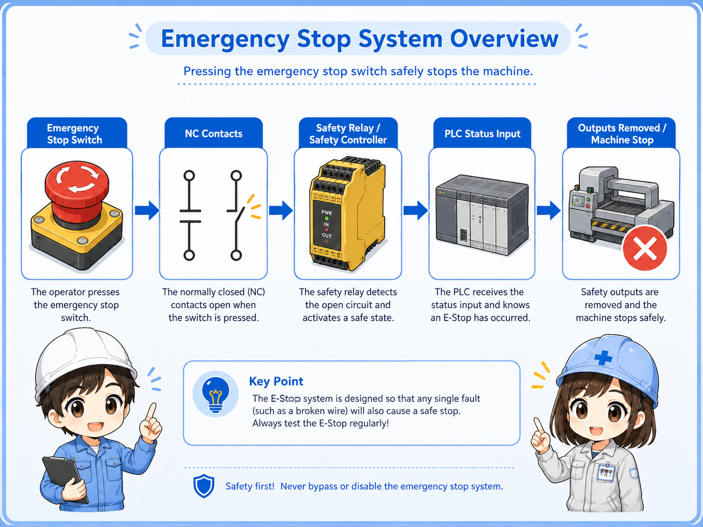
In many control panels, the emergency stop switch is a red mushroom-head pushbutton. Pressing it opens the emergency stop contact path and causes the control circuit, safety relay, or safety controller to remove the machine run permission.
The important point is that an emergency stop is not just a normal operation button. It belongs to the safety-related part of the control system, so it should be considered together with wiring, reset conditions, relays, contactors, PLC inputs, and the machine’s risk assessment.
Normal stop button vs emergency stop switch
A normal stop button and an emergency stop switch both stop operation, but their roles are different.
A normal stop button is usually part of everyday operation. For example, it may stop a conveyor at the end of work or stop a cycle during normal control.
An emergency stop switch is intended for abnormal or hazardous situations. It should bring the machine to a defined safe stop condition according to the machine design.
| Item | Normal stop button | Emergency stop switch |
|---|---|---|
| Main purpose | Stop operation during normal use | Stop dangerous operation in an emergency |
| Design meaning | Part of regular control logic | Part of a safety-related control concept |
| Common circuit | PLC input, relay circuit, or operation logic | Safety relay, safety controller, contactor removal, or safety input |
| Reset | Often starts again by normal operation | Usually requires a deliberate reset or release sequence depending on design |
Do not judge safety by appearance alone
A red mushroom button looks like an emergency stop, but the real safety function depends on the wiring, contacts, safety relay or controller, output devices, reset logic, and machine design.
Why NC contacts are commonly used
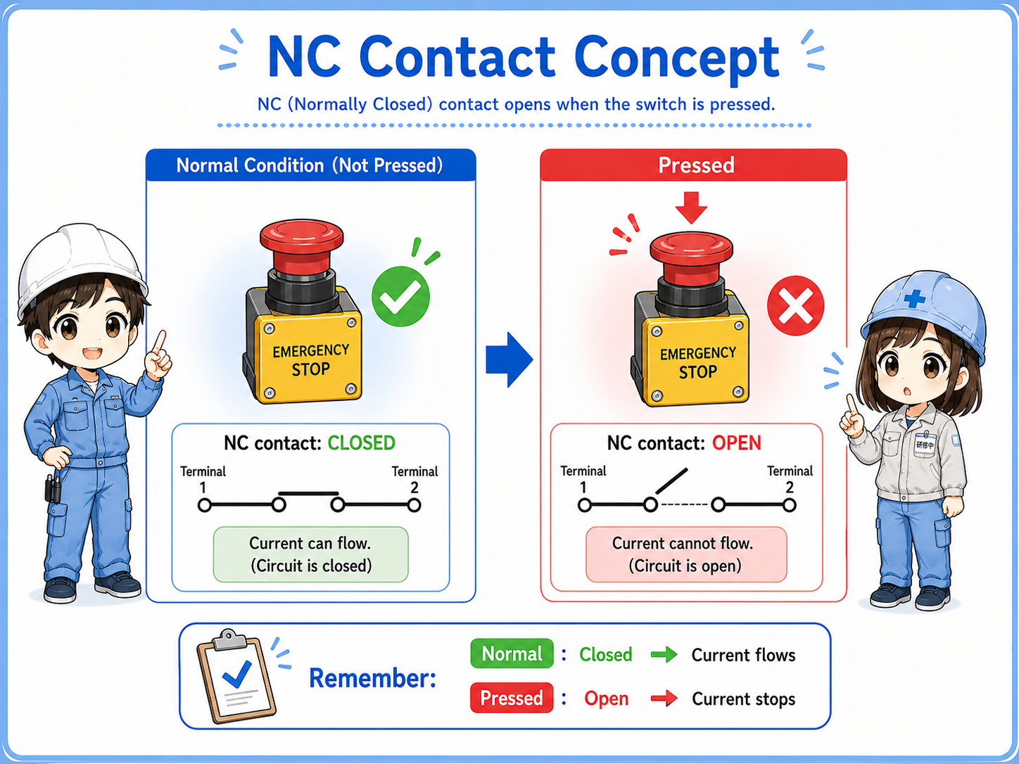
Emergency stop circuits commonly use normally closed contacts so the signal path opens when the button is pressed or when the path is interrupted.
In normal condition, an NC contact is closed. The control circuit can read this as “the emergency stop path is healthy” depending on the design.
When the emergency stop switch is pressed, the NC contact opens. That open condition is detected by a safety relay, safety controller, or input circuit, and the machine run permission is removed.
This is also useful for detecting some wiring faults. If a wire is broken in the emergency stop path, the path opens and the machine may stop or refuse to start instead of silently ignoring the problem.
Simple way to remember
Normal condition: NC path is closed. Emergency stop pressed: NC path opens. The open path tells the control system to remove permission to operate.
Basic emergency stop circuit flow
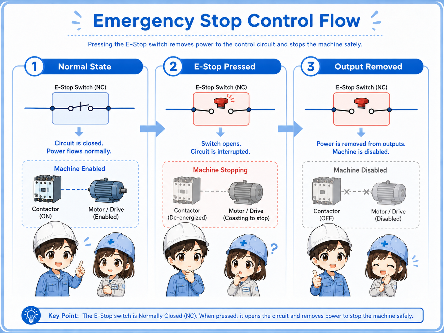
The exact design depends on the machine, but the basic flow can be understood step by step.
1. Normal state
The emergency stop contact path is closed and the safety device allows operation.
2. E-stop pressed
The NC contact opens and the safety device detects the stop condition.
3. Output removed
Run permission is removed, such as contactor control or machine enable output.
Do not bypass the emergency stop path casually
Never short-circuit or bypass emergency stop wiring just to make a machine run. Follow site rules and safety procedures, and involve qualified personnel when checking safety-related circuits.
Relation to safety relays and PLC inputs
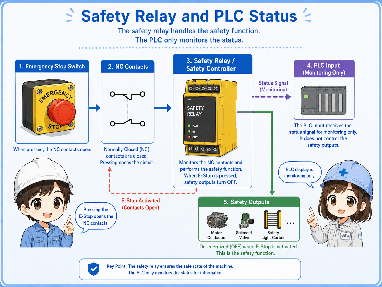
In real panels, an emergency stop switch may connect to a safety relay, safety controller, or safety PLC input, while a normal PLC may receive status information separately.
A safety relay or safety controller checks the emergency stop contact path and controls safety outputs. Those outputs may remove contactor coils, stop drives, or remove operation permission depending on the machine design.
A standard PLC input may also show “emergency stop pressed” or “safety relay ready” on a screen. However, this display signal should not be confused with the actual safety function.
Status display is not the whole safety function
A PLC screen may show emergency stop status, but the machine’s safety action depends on the actual safety circuit and output removal path.
Field check points
When checking an emergency stop problem, separate the button, contact path, safety device, reset condition, and output permission.
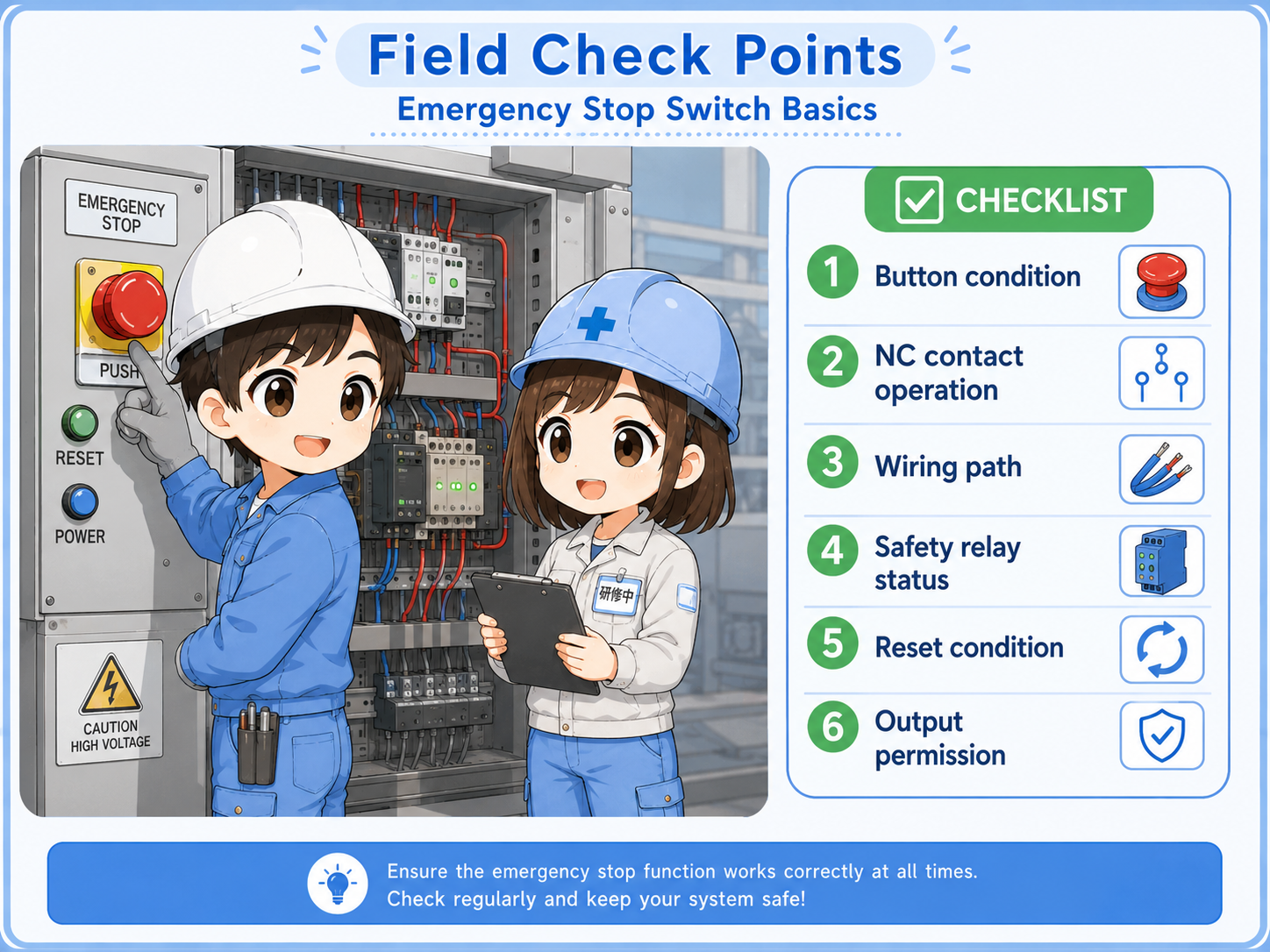
Button condition
Confirm whether the emergency stop switch is pressed, locked, damaged, or not fully released.
NC contact path
Check whether the NC contact closes in normal condition and opens when pressed.
Wiring path
Check terminals, loose wires, broken wires, and connector conditions in the emergency stop line.
Safety relay status
Check safety relay LEDs, input channels, output status, and reset condition according to the manual.
Reset condition
Confirm whether the system requires manual reset after the emergency stop is released.
Output permission
Check whether contactor coils, drive enable signals, or machine run permission are correctly removed and restored.
Common beginner mistakes
Emergency stop circuits can be misunderstood if they are treated like ordinary operation buttons.
- Thinking an emergency stop switch is the same as a normal stop button.
- Looking only at the PLC input and ignoring the safety relay or contactor output path.
- Assuming the red button alone guarantees safety.
- Forgetting that NC contacts are closed in normal condition and open when pressed.
- Trying to bypass the emergency stop circuit during troubleshooting.
- Ignoring reset conditions after the emergency stop is released.
Safety-related circuits require proper procedure
This article explains basic concepts only. Actual emergency stop design, inspection, and modification must follow applicable standards, machine design requirements, and site safety rules.
Short conversation

An emergency stop switch is not just a stronger stop button. It is part of the machine’s safety-related control path.

So even if the PLC shows the emergency stop input, that is not the whole safety function?
Exactly. The PLC may monitor status, but the actual stop action often depends on the safety relay, safety controller, contactors, and wiring.
And the NC contact opens when the emergency stop is pressed, right?
Yes. Normal condition is closed. Pressed, released incorrectly, broken wire, or open path means the circuit should not allow normal operation.
Summary
An emergency stop switch should be understood as part of a safety-related control concept, not only as a large red stop button. In many systems, NC contacts are closed during normal condition and open when the emergency stop is pressed.
In the field, separate the check into the button condition, NC contact path, wiring, safety relay or controller status, reset condition, and output permission. This makes troubleshooting clearer while keeping the safety-related nature of the circuit in mind.