1. The basic idea: one circuit controls another circuit
A relay is an electrical control part that uses a coil to switch contacts.
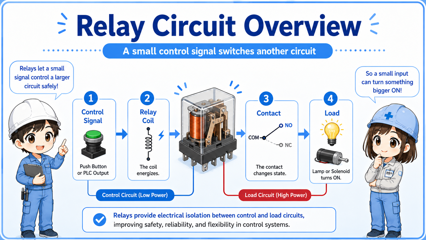
The easiest way to understand a relay is to separate it into two sides. The coil side receives the control signal. The contact side switches another circuit. These two sides work together, but they are not the same circuit.
Short version: coil ON → relay operates → contacts change state → another circuit is switched.
In control panels, relays are often used between PLC outputs and field devices, between control signals and loads, or inside basic circuits such as self-holding and interlock circuits.
- Relay coil
- NO contact
- NC contact
- Control signal
- Load circuit
The first question to ask
When reading a relay circuit, first ask: “What energizes the coil?” Then ask: “What does the contact switch when the coil changes state?”

Senior
Do not try to read the whole relay circuit at once. Start with the coil.

Junior
If the coil turns on, the contact state changes. That is the basic movement?
Senior
Exactly. Once that relationship is clear, relay drawings become much easier to follow.
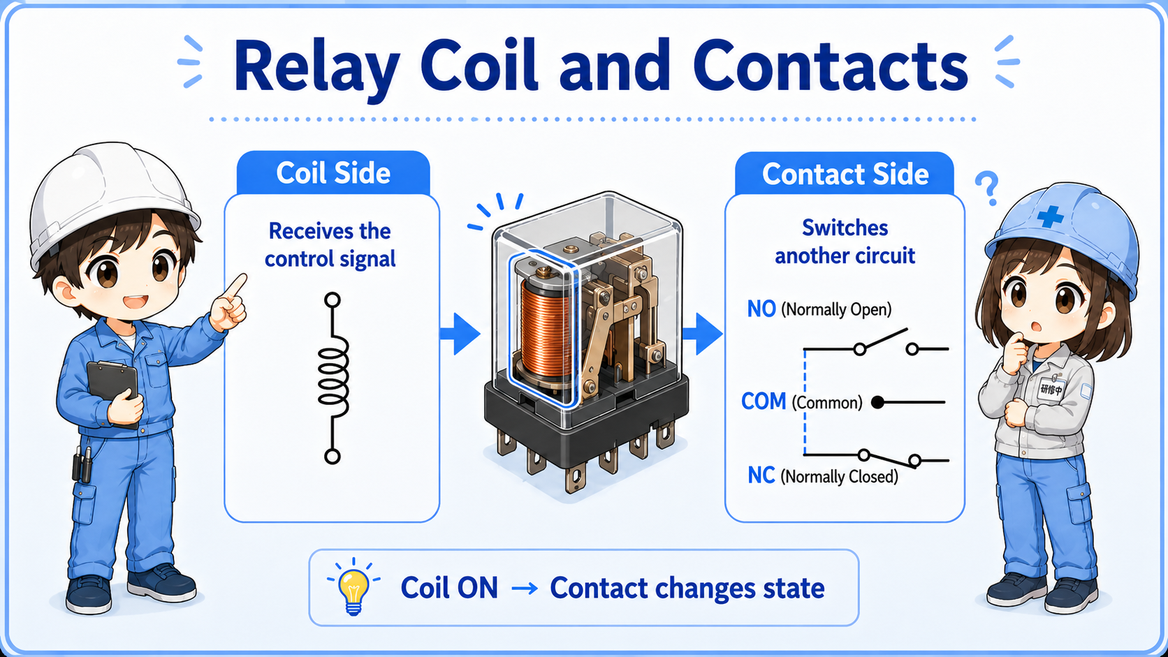
2. Coil and contacts: the two parts of a relay
The coil creates the relay action, and the contacts switch the target circuit.
Control signal ON
Voltage is applied to the relay coil from a switch, PLC output, or control circuit.
Coil energizes
The relay operates internally and changes the position of its contacts.
Contact switches
The contact opens or closes another circuit, such as a lamp, solenoid, or signal line.
Field-friendly view
If a relay does not seem to work, do not check only the load. Check whether the coil is energized and whether the correct contact actually changes state.
3. NO and NC contacts
Relay contacts are often described as normally open and normally closed.
A normally open contact is open when the relay is not energized, and closes when the relay operates. A normally closed contact is closed when the relay is not energized, and opens when the relay operates.
| Contact type | Relay coil OFF | Relay coil ON | Typical use |
|---|---|---|---|
| NO contact | Open | Closed | Turn something on when the relay operates. |
| NC contact | Closed | Open | Break a circuit, make an interlock, or detect relay operation. |
“Normally” means the coil is not energized
In relay language, “normal” usually means the relay coil is off. This is a common place where beginners get confused.
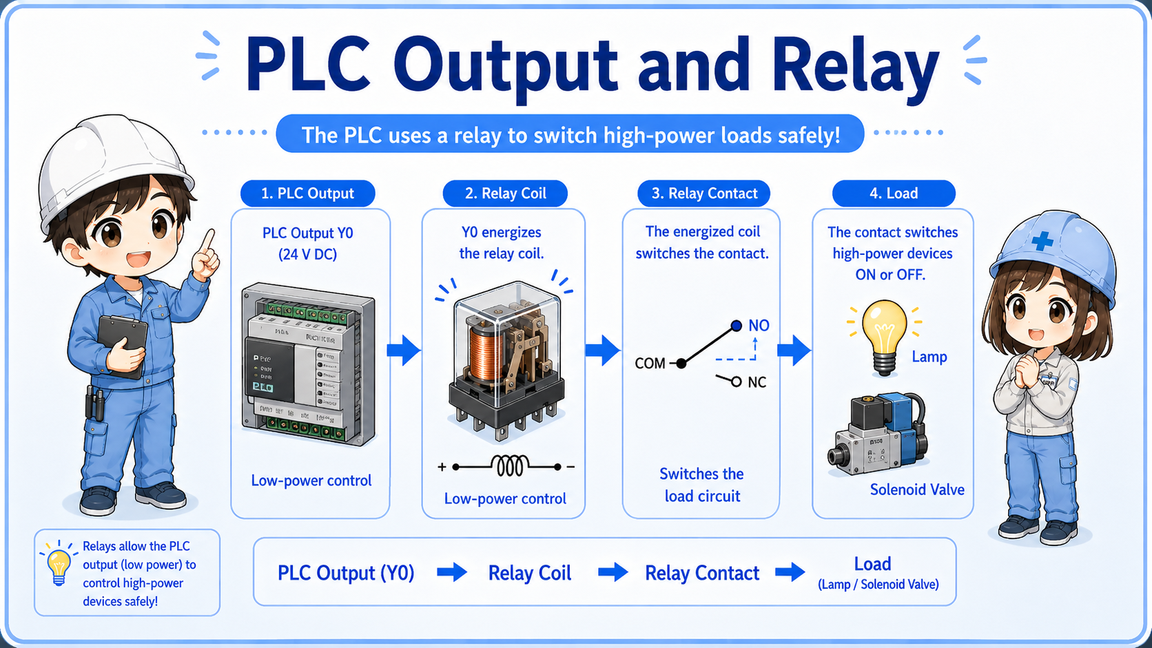
4. Relays and PLC outputs
A PLC output may drive a relay coil so the relay contacts can switch another circuit.
In many control panels, the PLC does not directly switch every load. A PLC output may energize an intermediate relay. Then the relay contact switches a signal, lamp, solenoid valve, or another control circuit.
Why use an intermediate relay?
It can help separate circuits, make wiring easier to understand, allow multiple contacts to be used, and protect the PLC output from being the only switching point.
5. Relay vs contactor
Relays and contactors both use coils and contacts, but they are not used in exactly the same way.
A small relay is often used for control signals and smaller loads. A contactor is generally used for larger loads such as motors or heaters. The exact selection depends on voltage, current, load type, contact rating, and the equipment design.
| Device | Typical role | Beginner-friendly way to see it |
|---|---|---|
| Relay | Switches control signals or smaller loads. | Often used inside control circuits and PLC-related wiring. |
| Contactor | Switches larger power loads such as motors. | A larger switching device for load circuits. |
Always check ratings
Do not choose a relay only by appearance. Check coil voltage, contact rating, load type, wiring diagram, socket type, and the manufacturer's specifications.
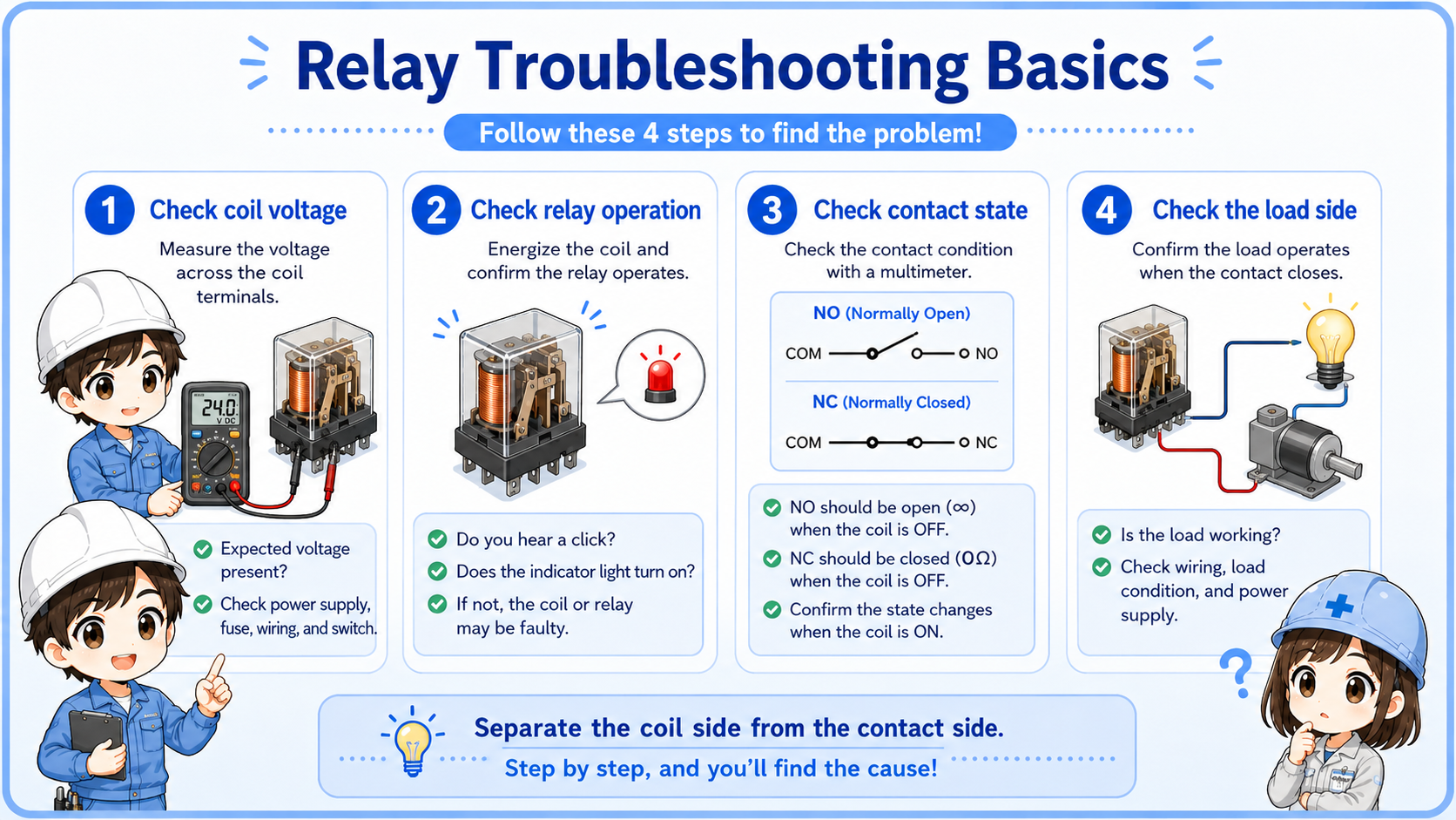
6. Troubleshooting relay circuits
Relay troubleshooting is easier when you separate the coil side from the contact side.
1. Check coil voltage
Is the correct voltage actually applied to the relay coil?
2. Check relay operation
Does the relay indicator turn on, or can you confirm the relay is operating?
3. Check contact state
When the coil turns on, does the NO or NC contact change as expected?
4. Check the load side
If the contact switches, is the downstream lamp, valve, contactor, or signal line working?
Junior
The relay lamp is on, but the device does not move. Is the relay definitely okay?
Senior
Not always. The coil may be energized, but you still need to check whether the contact is switching and whether the load-side wiring is correct.
7. Practical safety notes
Relay circuits may involve different voltages and load circuits, so checks must be done carefully.
A relay can connect a low-voltage control signal to a separate load-side circuit. Always follow drawings, site procedures, lockout/tagout rules, and the equipment manufacturer's documentation before measuring or replacing relays.
Keep learning in layers
Relay circuits become much easier after you understand NO/NC contacts, PLC inputs and outputs, self-holding circuits, interlocks, and basic ladder reading.