What a start/stop circuit does
The job of a start/stop circuit is simple: start an output with a momentary command, then keep it on until a stop command breaks the path.
In a basic control panel, the operator often presses a start button only for a moment. If the circuit only depended on that button, the output would turn off as soon as the button was released.
A start/stop circuit solves this by using a self-holding contact. After the output turns on, an auxiliary contact creates another path that keeps the output energized.
This idea appears in motor start/stop operation, conveyor commands, lamp circuits, relay control, PLC internal logic, and many basic machine-control sequences.
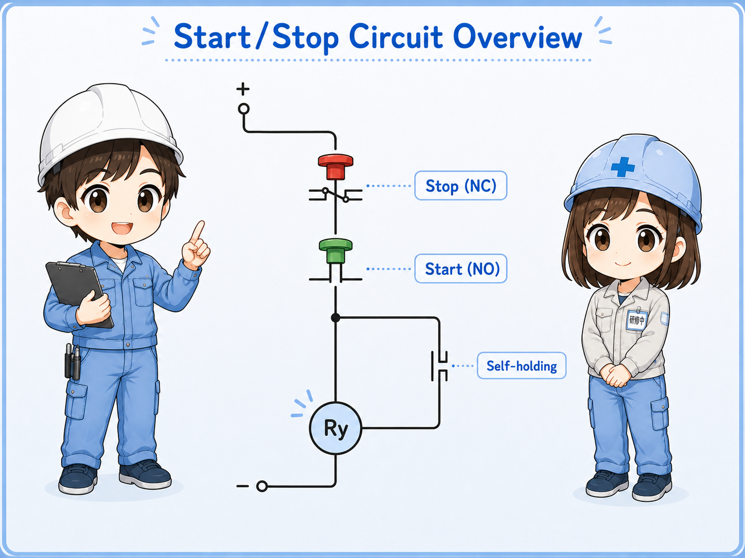
Main parts of the circuit
The basic circuit is easier to understand when each part has a clear role.
- Stop button
- Start button
- Output coil
- Self-holding contact
| Part | Usual contact type | Role in the circuit |
|---|---|---|
| Stop pushbutton | NC contact | Normally closed during normal operation. Pressing stop opens the path and turns the output off. |
| Start pushbutton | NO contact | Normally open. Pressing start closes the path and gives the first ON command. |
| Output coil | Relay, contactor, PLC internal relay, or output command | Turns on when the circuit path is complete. |
| Self-holding auxiliary contact | Usually NO auxiliary contact linked to the output | Closes after the output turns on and keeps the circuit energized after the start button is released. |
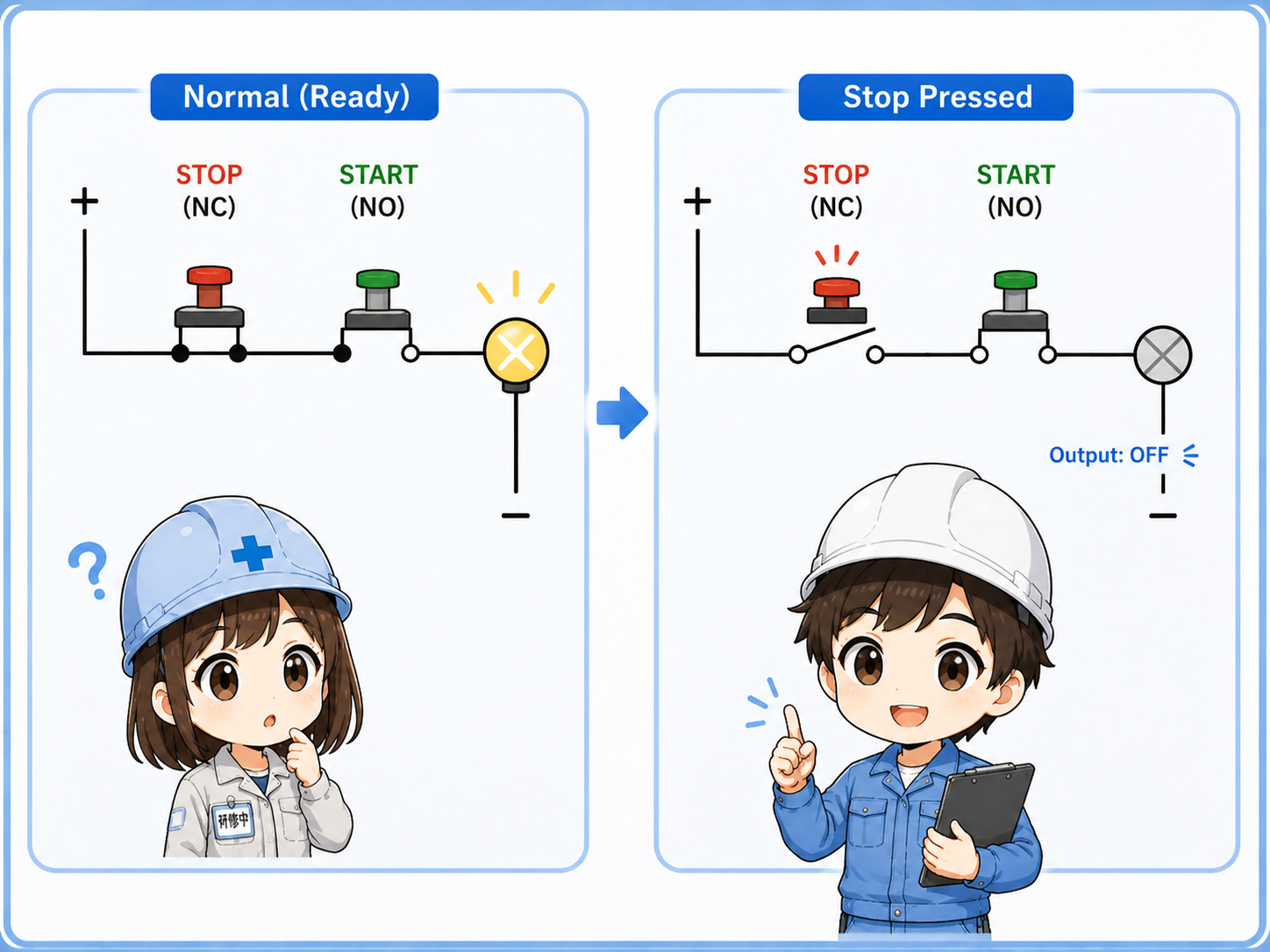
Why the stop button is normally closed
In many basic control circuits, the stop button is placed before the start command and is normally closed.
When everything is normal, the stop path is already closed. That means the circuit is ready to receive a start command. When the operator presses stop, the NC contact opens and the output drops out.
This also makes certain open-circuit problems easier to notice. For example, if a wire in the stop path is broken, the circuit may fail to start or may drop out instead of silently ignoring the stop path.
Important note
A normally closed stop button is a basic control-circuit idea. It does not, by itself, make a machine safe. Safety circuits, emergency stops, risk assessment, and standards must be designed separately.
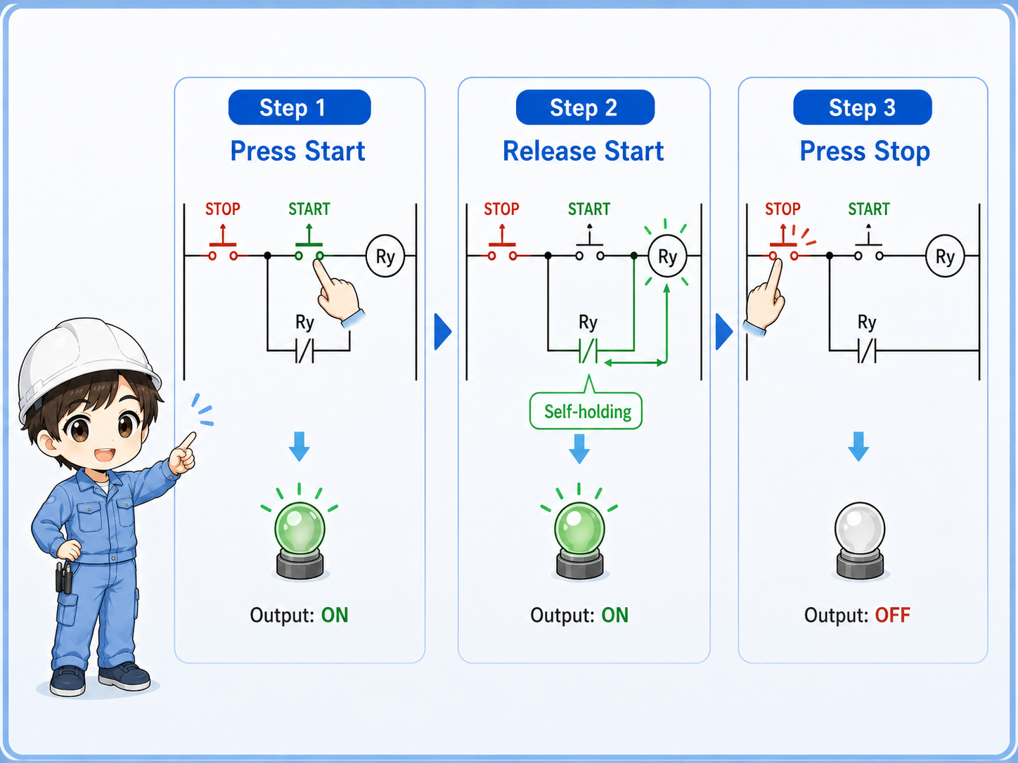
How self-holding works
Self-holding is the part that keeps the output on after the start button is released.
The start button closes only while it is being pressed. Once the output coil turns on, an auxiliary contact linked to that output also closes. This auxiliary contact is placed in parallel with the start button.
After that, releasing the start button does not stop the circuit. Current or logic continuity can still pass through the self-holding contact. The output stays on until the stop button opens the path.
Simple way to remember
The start button turns the output on once. The self-holding contact keeps it on. The stop button breaks the path and turns it off.
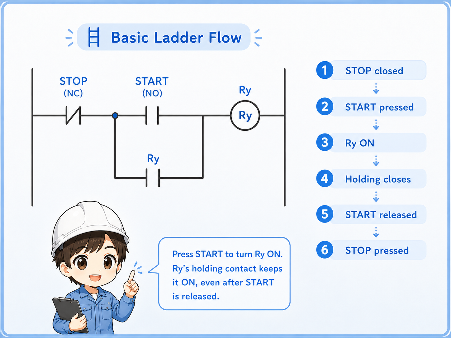
Basic ladder flow
The same idea can be followed as a simple ladder-logic flow without depending on a specific PLC brand.
1. Ready state
The stop contact is closed, but the start button is still open.
2. Start command
Pressing start closes the command path and turns the output on.
3. Holding state
The auxiliary contact closes and keeps the output energized.
Common places this circuit appears
Start/stop logic is a basic pattern that appears in many practical control panels and PLC programs.
Motor start/stop operation
Often used before driving a contactor or motor command, together with protection and interlocks.
Conveyor start/stop command
A start button begins operation, while stop or interlock conditions remove the run command.
Control panel pushbuttons
Operator panels commonly use separate start and stop buttons for clear manual control.
PLC internal logic
The same structure can be used as internal logic before turning on a real PLC output.
Field check points
When a start/stop circuit does not work, check the path in order instead of guessing from the output side only.
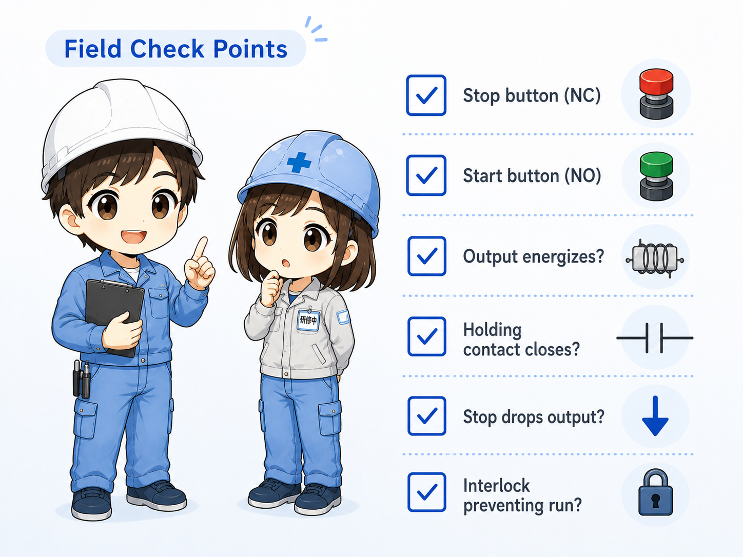
Stop button contact
Confirm the NC contact is wired correctly and closes during normal operation.
Start button contact
Confirm the NO contact closes only while the start button is pressed.
Output behavior
Check whether the output energizes only while pressing start, or remains on after release.
Holding contact
Confirm the auxiliary or internal holding contact closes after the output turns on.
Stop operation
Press stop and verify the output reliably drops out.
Interlock conditions
Check whether an emergency stop, guard, overload, or interlock is preventing operation.
Common beginner mistakes
Most start/stop circuit mistakes come from mixing up contact type, contact position, or the meaning of PLC input status.
- Using an NO contact for the stop button by mistake.
- Forgetting the self-holding contact, so the output turns off when the start button is released.
- Placing the self-holding contact in the wrong position.
- Confusing a physical NC contact with how the signal appears in the PLC monitor.
- Assuming the output coil is bad without checking the stop and start path first.
Do not bypass stop or safety-related circuits casually
For troubleshooting, always follow your site rules. Do not temporarily bypass stop, emergency stop, or interlock wiring unless the work is properly controlled and authorized.
Short conversation

If the motor stops as soon as you release the start button, the first thing I would check is the holding path.

So the start button itself is not supposed to keep the motor running?
Right. The start button only gives the first command. After the output turns on, the self-holding contact keeps the command path closed.
And the stop button is normally closed because the circuit should open when we press stop?
Exactly. During normal operation the stop path is closed. Pressing stop opens that path and drops the output.
Summary
A start/stop circuit is a basic but important control pattern. The start button gives the initial command, the stop button breaks the command path, and the self-holding contact keeps the output on after the start button is released.
In the field, troubleshooting becomes much easier when you separate the circuit into four parts: the stop path, the start path, the output coil, and the holding contact.