What is a flicker circuit?
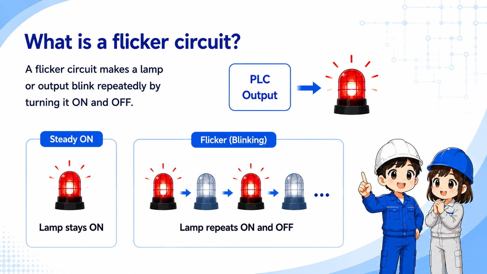
A flicker circuit is a basic circuit that makes a lamp or output blink repeatedly.
In a normal lamp circuit, the lamp turns ON and stays ON while the output is ON. In a flicker circuit, the lamp repeats ON and OFF so it is easier to notice.
Flicker circuits are often used for alarm lamps, warning lamps, attention signals, and simple machine status indication.

A flicker circuit is not just “lamp ON.” It is a repeated ON and OFF pattern. That blinking makes the signal easier to notice in the field.

So when I check it, I should look at the enable condition, the timer or clock signal, and the final lamp output.
Timer flow: ON time and OFF time
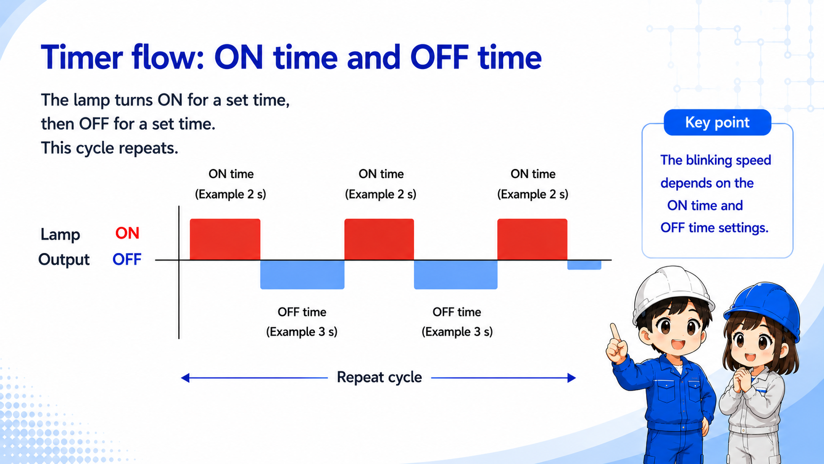
The basic idea is to repeat a lamp ON period and a lamp OFF period.
A simple flicker pattern can be made by alternating between an ON timer and an OFF timer, or by using an internal clock bit prepared by the PLC.
| State | Timer idea | Lamp output | Field image |
|---|---|---|---|
| ON period | The circuit allows the lamp output. | Lamp ON | The warning or indication is visible. |
| OFF period | The circuit blocks the lamp output. | Lamp OFF | The lamp goes dark for a short time. |
| Repeat | The cycle starts again. | ON/OFF repeats | The lamp appears to blink. |
Beginner takeaway
A flicker circuit is basically a repeated ON/OFF signal used to make a lamp flash or blink. It is easier to understand if you separate it into the “condition to blink” and the “timer or clock signal that creates the blinking.” Check the ON time and OFF time separately, because changing either one changes the visible blinking speed.
Basic ladder logic idea
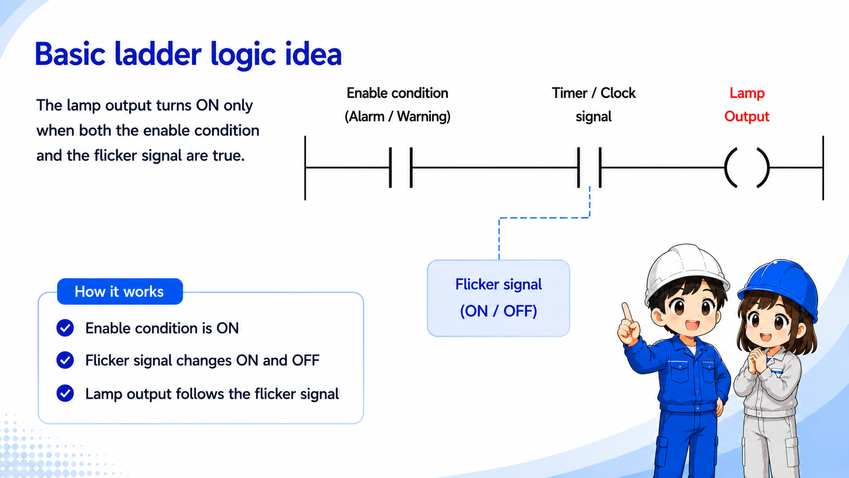
The lamp output usually turns ON only when both the enable condition and the flicker signal are true.
In PLC ladder logic, the alarm or request condition may enable the flicker circuit. Then a timer bit, clock bit, or internal relay creates the repeated ON/OFF signal.
The final lamp output is driven by the combination of the enable condition and the flicker signal.
PLC instruction names differ
Different PLCs may use timers, clock pulses, special relays, or internal bits to create a flashing or flicker signal. Do not assume that the same device name or instruction name can be reused across PLC models. Always check the actual PLC project, wiring diagram, machine specification, and manufacturer manual before changing the logic.
Where flicker circuits are used
Blinking is often used when the operator needs to notice a condition quickly.
| Use case | Why blink? | What to check |
|---|---|---|
| Alarm indication | A blinking lamp draws attention more strongly than steady ON. | Alarm condition, flicker signal, lamp output. |
| Warning or caution | The machine can show that action or confirmation is needed. | Warning condition and timer setting. |
| Operation status | Blinking may show waiting, ready, or in-progress status. | Mode condition and output assignment. |
Do not judge only by the lamp
If the lamp does not blink, the issue may be the request condition, timer logic, PLC output, wiring, lamp unit, or power supply.
Field checks when the lamp does not blink
Check the enable condition, flicker signal, output coil, wiring, and lamp side in order.
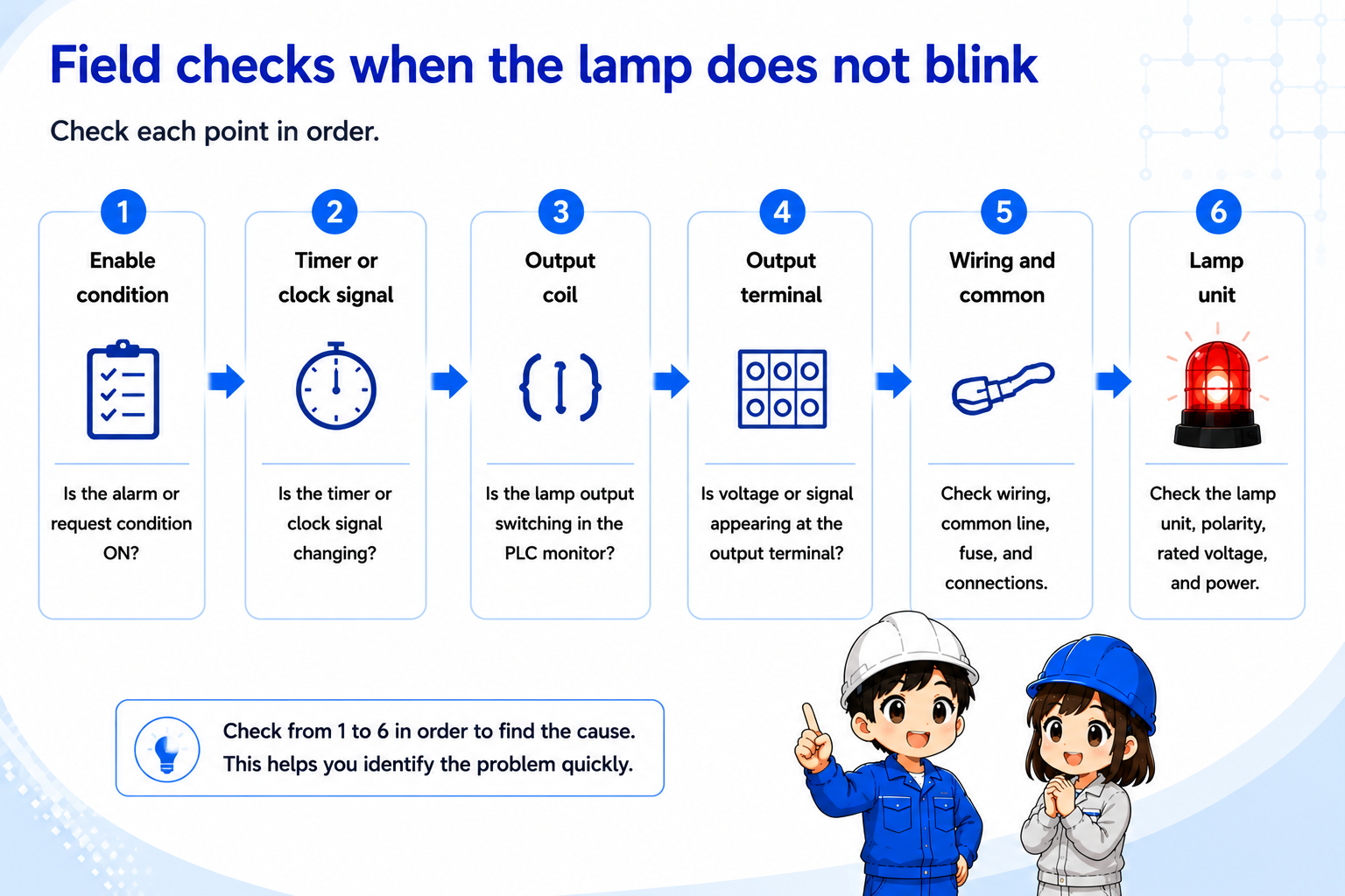
1. Enable condition
Confirm whether the alarm, warning, or status condition that should start blinking is actually ON.
2. Timer or clock signal
Check whether the timer bit, clock bit, or internal flicker signal is changing ON and OFF.
3. Output coil
Watch the PLC monitor and confirm whether the final lamp output is switching.
4. Output terminal
Check whether voltage or signal appears at the output terminal during the ON period.
5. Wiring and common
Check wiring, common line, fuse, terminal looseness, and output module side.
6. Lamp unit
Check the lamp, LED unit, polarity, rated voltage, and local power supply.
Be careful with alarm meanings
A blinking lamp may indicate a machine alarm, stop condition, or operator action request. Do not clear or bypass the condition before understanding what it means.
Summary
A flicker circuit repeatedly turns a lamp or output ON and OFF. It is often used for alarms, warnings, and attention signals.
In PLC control, the circuit is easier to read if you separate the enable condition from the timer or clock signal that creates the blinking.
Final takeaway
When a flicker circuit does not work, do not look only at the lamp. Check the request condition, flicker signal, output, wiring, and lamp unit as one chain.
Related articles
Read these next to connect flicker circuits with timer logic, outputs, and basic PLC troubleshooting.