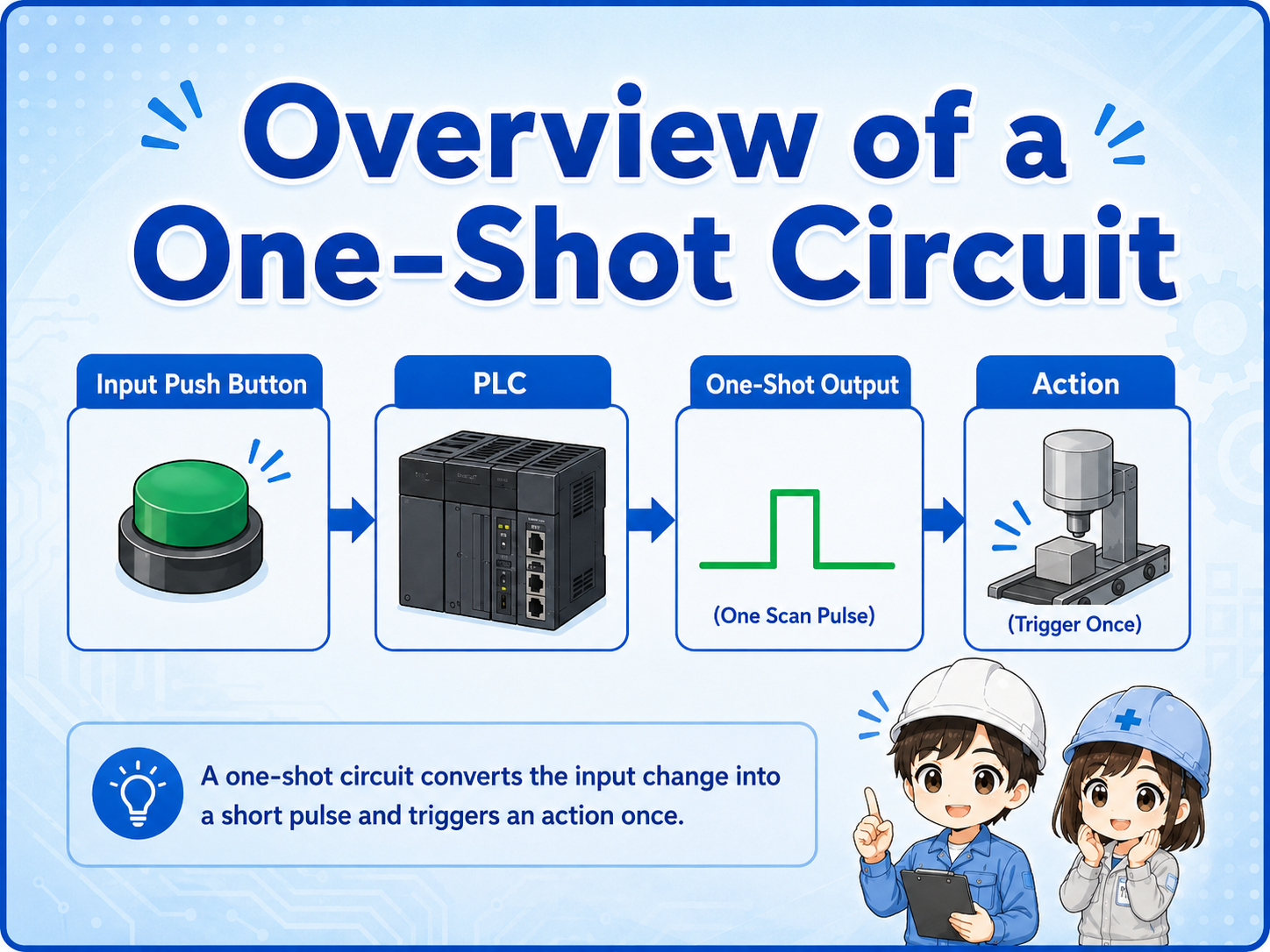
What is a one-shot circuit?
A one-shot circuit creates a short pulse signal when an input changes state.
In PLC control, a one-shot signal is often used when you want an action to happen only once. For example, you may want to count one product, start one step, reset one value, or trigger one internal bit only at the moment a button turns ON.
The important point is that a one-shot is different from a normal input contact. A normal input may stay ON as long as the button is pressed, but a one-shot signal turns ON only for one scan or one short timing.
Why the PLC scan matters
A PLC reads inputs, executes the program, updates outputs, and repeats this cycle many times.
The word “one-shot” is closely related to the PLC scan. In many ladder programs, a one-shot bit becomes ON for only one program scan. This is why it can trigger an action once and then return OFF automatically.
The exact instruction name depends on the PLC manufacturer, but the practical concept is the same: detect a change and create a short pulse.
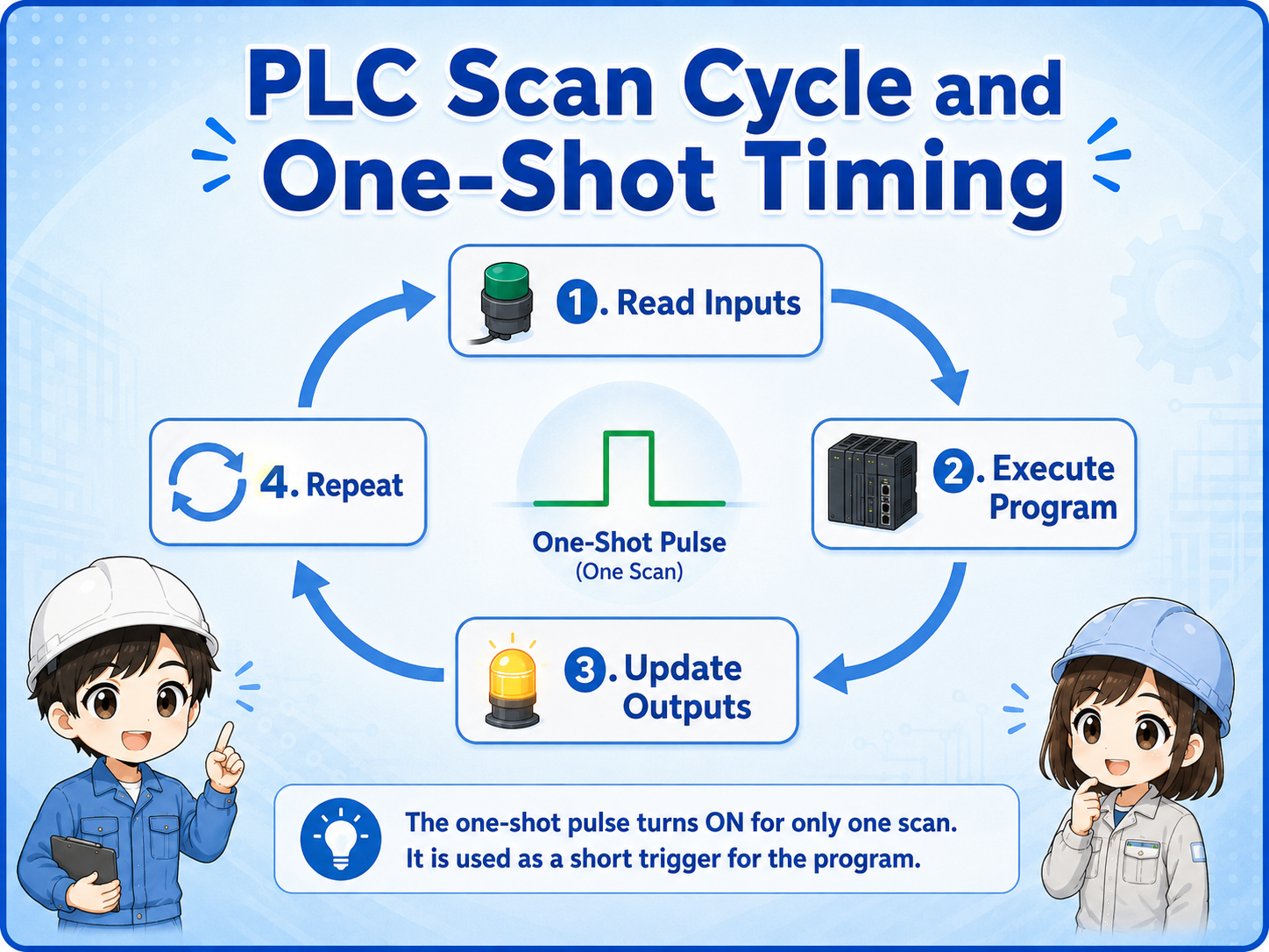
One scan does not mean one second
A PLC scan is usually much shorter than one second. A one-shot pulse may be too fast to see on a lamp, but it is enough for the PLC program to use internally.
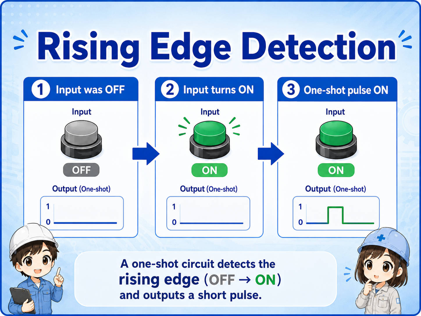
Rising-edge detection
A common one-shot pattern is created when an input changes from OFF to ON.
The rising edge is the moment an input changes from OFF to ON. A one-shot circuit detects this change and turns ON a pulse bit only at that moment.
This is useful because the machine can react once when the button is pressed, instead of repeating the action for as long as the button stays pressed.
1. Input was OFF
The PLC remembers that the input was OFF in the previous scan.
2. Input turns ON
The PLC detects the change from OFF to ON.
3. Pulse turns ON
A one-shot signal is created for a short timing.
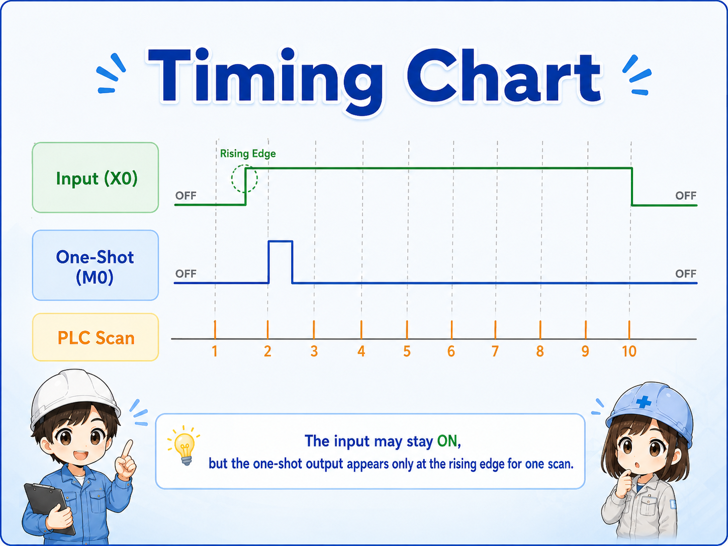
One-shot timing chart
A timing chart makes the difference between a normal input and a one-shot pulse easier to see.
When a push button is pressed and held, the input may stay ON for several scans. The one-shot output turns ON only at the beginning, then turns OFF even while the input remains ON.
Do not use a one-shot when you need continuous output
If the load must stay ON while a button is pressed, a one-shot is not the right pattern. Use a normal contact or a press-and-hold circuit instead.
One-shot, self-holding, and press-and-hold
These circuit patterns look similar at first, but their behavior is different.
A press-and-hold circuit turns ON while the input is ON. A self-holding circuit keeps the output ON after the start input is released. A one-shot circuit creates only a short pulse.
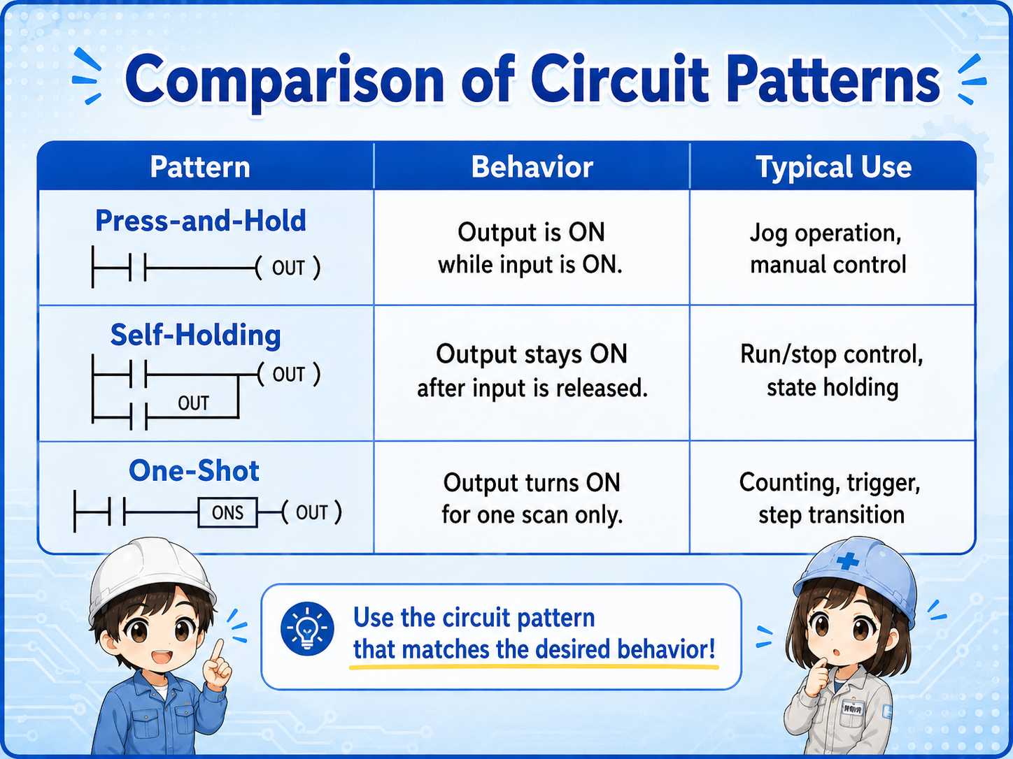
| Pattern | Behavior | Typical use |
|---|---|---|
| Press-and-hold | Output is ON while the input is ON. | Jog operation, manual operation, temporary movement. |
| Self-holding | Output stays ON after the start input is released. | Run/stop control, holding a machine state, basic motor control. |
| One-shot | Output turns ON only for one short timing. | Counting, trigger signals, step transitions, reset pulses. |
Common uses of a one-shot signal
One-shot signals are useful when repeated execution would cause problems.
If a command repeats every scan while an input is ON, the result may be wrong. A counter may count many times, a reset may repeat, or a step may advance unexpectedly. A one-shot signal prevents that by allowing the action only once.
Counter input
Count one event when the input turns ON, instead of counting every scan.
Step transition
Move to the next sequence step once when a condition becomes true.
Reset pulse
Send a short reset signal without keeping the reset condition ON.
Trigger command
Start one internal process, data capture, or command request at a specific timing.
Field check points
One-shot problems are often timing problems, not wiring problems.
In the field, the input lamp may turn ON normally, but the one-shot pulse may be too short to see. Use the PLC monitor, device monitor, or ladder status carefully.
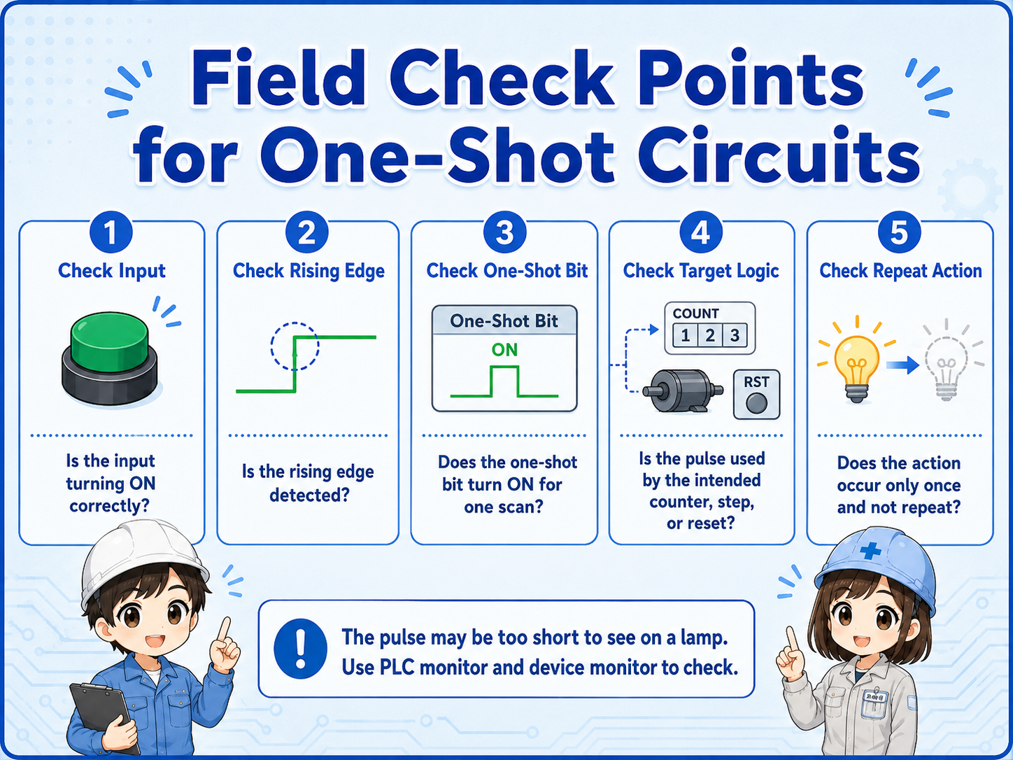
Practical check order
First confirm the input turns ON. Then check whether the rising edge is detected, whether the one-shot bit turns ON for one scan, and whether the target logic uses that pulse correctly.
- Confirm the actual push button or sensor input turns ON.
- Check whether the one-shot instruction or edge detection is placed in the correct rung.
- Check whether the pulse is used by the intended counter, reset, step, or internal relay.
- Check whether the same pulse is accidentally used in multiple places.
- Remember that a one-shot pulse may be too fast to judge from a physical lamp.
Short conversation

A one-shot circuit is used when you want the PLC to react only once at the moment an input turns ON.

So even if I keep pressing the button, the pulse does not stay ON?
Right. The normal input can stay ON, but the one-shot bit turns ON only for a short timing.
That means it is useful for counters and step transitions?
Exactly. It prevents repeated execution while the input remains ON.
Summary
A one-shot circuit creates a short pulse signal, often for one PLC scan. It is commonly used to trigger an action once when an input changes from OFF to ON.
When checking a one-shot circuit, separate the normal input state, rising-edge detection, one-shot pulse, and target logic. The pulse may be too fast to see with a lamp, so PLC monitoring is important.