What a forward and reverse circuit does
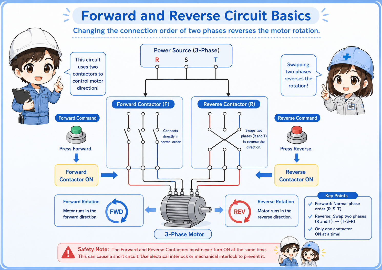
A forward and reverse circuit changes the rotation direction of a three-phase motor by changing the phase order.
In a typical circuit, one contactor is used for forward rotation and another contactor is used for reverse rotation. When the forward contactor turns on, the motor receives the phase order for forward rotation. When the reverse contactor turns on, two phases are swapped so the motor rotates in the opposite direction.
The important point is that the forward and reverse contactors must not turn on at the same time. If both contactors operate together, it can create a short circuit or serious equipment damage.
Forward and reverse contactor roles
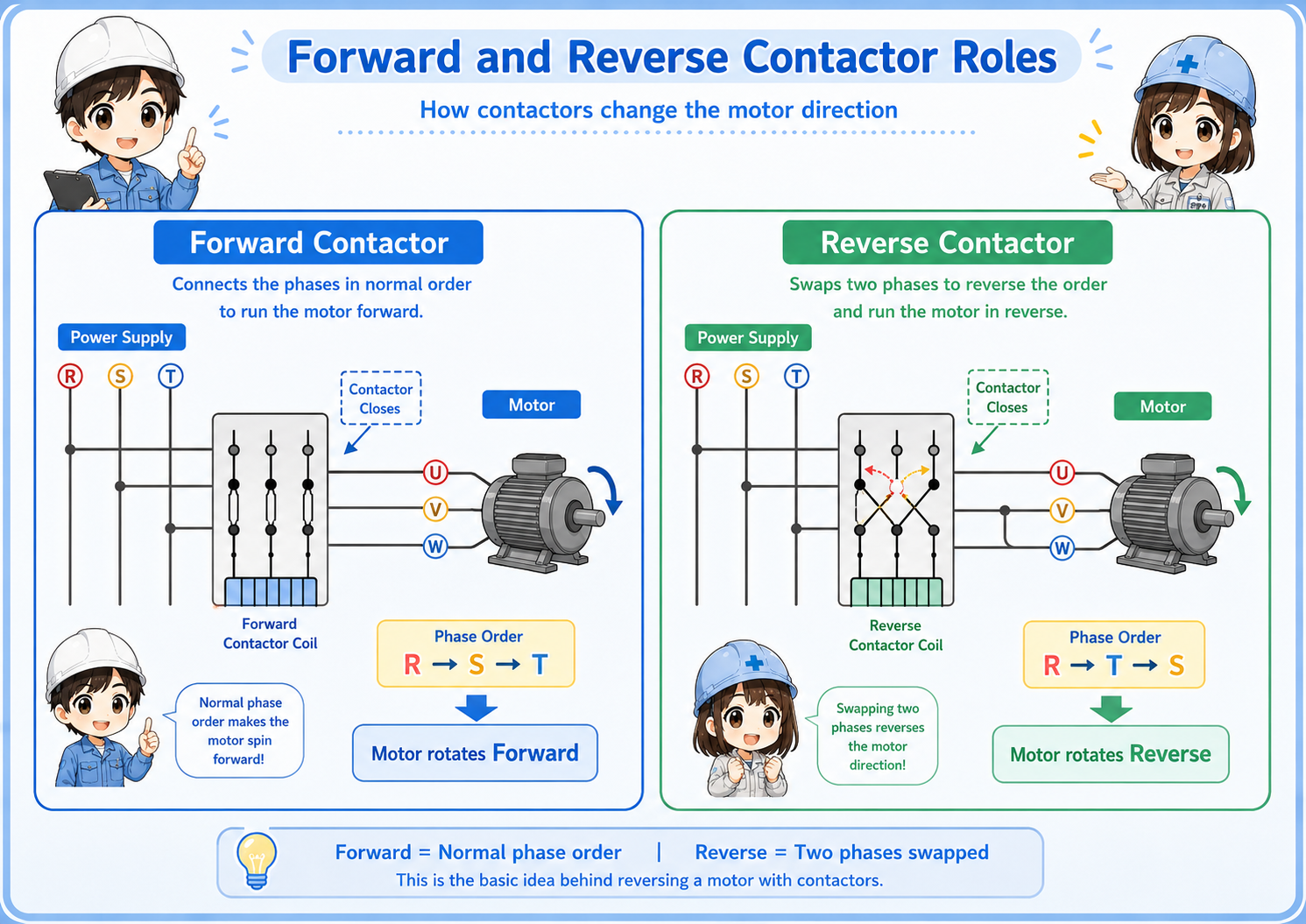
The circuit usually has one contactor for forward rotation and one contactor for reverse rotation.
The forward contactor connects the motor phases in the normal order. The reverse contactor swaps two phases. This phase swap changes the rotation direction of a three-phase motor.
The control side may be made with push buttons, relays, timers, or PLC outputs. But the basic role of the two contactors stays the same.
| Part | Basic role | Field check |
|---|---|---|
| Forward contactor | Turns the motor in the forward direction. | Check coil command, auxiliary contacts, main contacts, and output wiring. |
| Reverse contactor | Turns the motor in the reverse direction by changing the phase order. | Check that it does not turn on while the forward side is active. |
| Motor | Changes rotation direction according to the phase order. | Check actual rotation direction after wiring or maintenance work. |
Interlock is the most important part
Interlock prevents the forward and reverse sides from turning on at the same time.
A forward/reverse circuit normally uses an electrical interlock with auxiliary contacts. For example, the reverse contactor’s normally closed auxiliary contact can be placed in the forward coil circuit, and the forward contactor’s normally closed auxiliary contact can be placed in the reverse coil circuit.
Many reversing contactor sets also use a mechanical interlock. This physically prevents both contactors from closing together.
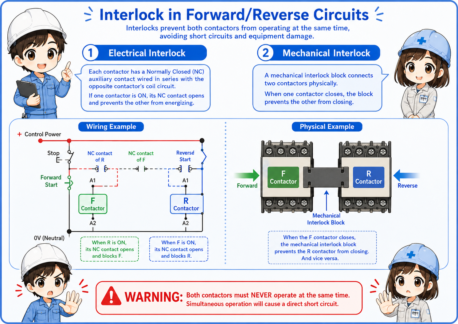
Never remove the interlock casually
In a forward/reverse circuit, interlock is not optional decoration. It is a protection idea that prevents dangerous simultaneous operation.
Self-holding and stop behavior
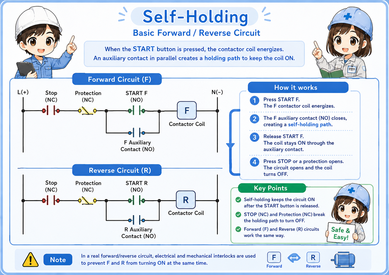
Many forward/reverse circuits use self-holding so the motor keeps running after the start button is released.
In a relay circuit, the contactor’s auxiliary contact is often used to keep the coil energized after the start button is pressed. This is called self-holding or seal-in.
The stop button, overload contact, emergency stop circuit, or PLC stop condition can break this holding path and stop the motor.
Simple way to remember
The start command chooses the direction. The self-holding contact keeps it running. The stop or protection contact releases it.
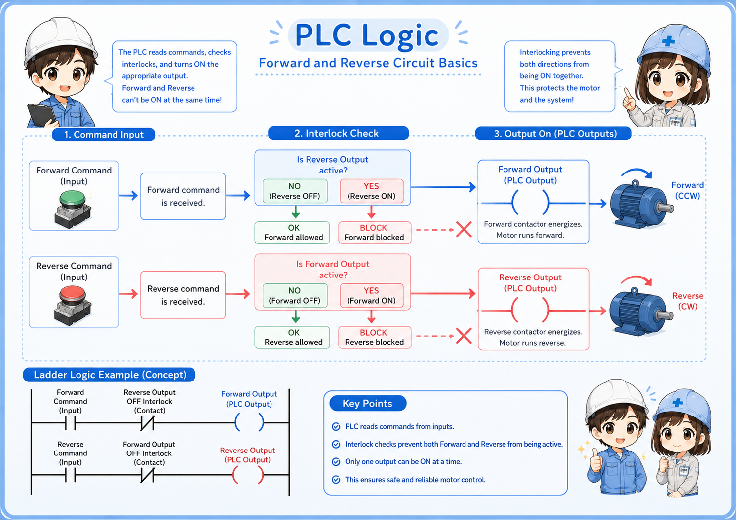
PLC logic should also include interlock
Even when a PLC controls the forward and reverse outputs, the same interlock idea is needed.
In PLC logic, the forward output should not be allowed to turn on while the reverse output is active. The reverse output should not be allowed to turn on while the forward output is active.
In real machines, it is common to use both PLC logic interlock and hardwired interlock. The PLC helps control the sequence, while the wiring and contactor arrangement provide an additional practical layer of protection.
1. Command
The operator or sequence requests forward or reverse operation.
2. Interlock check
The opposite direction must not already be active.
3. Output ON
The PLC or relay circuit turns on only the allowed direction.
Field check points
When a forward/reverse circuit does not work as expected, check command, interlock, contactor, wiring, and motor direction separately.
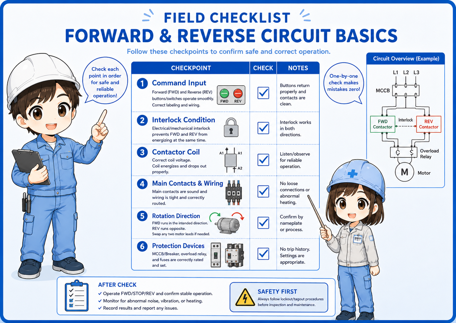
Command input
Check whether the forward or reverse command is actually being requested.
Interlock condition
Confirm that the opposite direction contact or PLC output is not blocking operation.
Contactor coil
Check coil voltage, coil wiring, auxiliary contacts, and contactor movement.
Main contacts and wiring
Check phase wiring, terminal tightening, contact wear, and wiring mistakes.
Rotation direction
After wiring work, confirm the actual motor direction before normal operation.
Protection devices
Check motor breaker, thermal relay, overload contact, and related alarms.
Common beginner mistakes
Forward/reverse circuits become dangerous when the interlock idea is treated lightly.
- Thinking forward and reverse are only two simple output signals.
- Forgetting to check the normally closed interlock contacts.
- Only checking PLC logic and ignoring hardwired contactor interlock.
- Changing motor wiring without confirming the actual rotation direction.
- Assuming the contactor is bad before checking command and stop conditions.
- Removing or bypassing interlock contacts during troubleshooting.
Use the actual drawing
Forward/reverse circuits can be built with relay logic, PLC logic, inverter commands, or dedicated reversing contactor units. Always check the actual machine drawing and manual.
Short conversation

In a forward/reverse circuit, the biggest danger is both directions turning on together.

That is why we use interlock contacts, right?
Exactly. Electrical interlock and mechanical interlock both help prevent simultaneous operation.
Even if the PLC logic is correct, I should still check the real contactor wiring?
Yes. PLC logic, auxiliary contacts, mechanical interlock, and actual wiring all matter in the field.
Summary
A forward and reverse circuit changes the motor direction by using two contactors and changing the phase order. The forward contactor and reverse contactor must never turn on at the same time.
The most important concept is interlock. When troubleshooting, separate the check into command input, PLC logic, interlock contacts, contactor operation, power wiring, protection devices, and actual motor direction.