1. The basic idea: do not allow conflicting operations
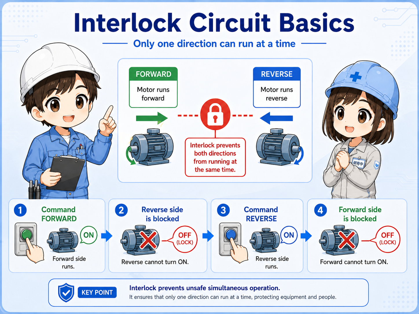
An interlock is a condition that prevents an output from turning on when another operation should take priority or must not happen at the same time.
In control circuits, some operations cannot safely happen together. For example, a motor should not be commanded forward and reverse at the same time. A clamp should not open and close at the same time. Two contactors that would short a circuit must not energize together.
Short version: an interlock is a blocking condition that prevents an unsafe or conflicting command.
The important point is that an interlock is not only a component. It is a control idea. It can be made with relay contacts, auxiliary contacts, PLC logic, mechanical interlock parts, or a combination of these.
- Interlock
- Blocking condition
- Conflicting outputs
- Forward / reverse
The easiest way to remember it
A self-holding circuit keeps an output on. An interlock circuit prevents another output from turning on. These two ideas are often used together, but their roles are different.

Senior
When you read an interlock, ask this first: “What is this circuit trying to prevent?”

Junior
So it is not just a contact. It is there to stop a conflicting operation?
Senior
Exactly. Once you know what must be blocked, the circuit becomes much easier to read.
2. Why interlocks are needed
Interlocks are used because some commands are dangerous, mechanically impossible, or electrically wrong if they happen together.
In real equipment, control logic is not only about turning outputs on. It is also about preventing the wrong output from turning on. Interlocks help protect equipment, prevent incorrect movement, and make troubleshooting more predictable.
| Situation | What must be prevented | Typical reason |
|---|---|---|
| Forward / reverse motor | Forward and reverse contactors turning on together. | Prevents electrical conflict and wrong motor command. |
| Open / close actuator | Open and close commands being active together. | Prevents conflicting motion commands. |
| Auto / manual mode | Two control sources commanding the same output at the same time. | Keeps operation mode clear and easier to troubleshoot. |
Field-friendly view
When an output does not turn on, the circuit may not be broken. It may be intentionally blocked by an interlock condition.
3. Common example: forward and reverse interlock
The forward/reverse motor circuit is one of the easiest examples for understanding interlock thinking.
In a forward/reverse circuit, the forward output and reverse output should not be energized at the same time. A common way to prevent this is to put the reverse-side normally closed contact in the forward circuit, and the forward-side normally closed contact in the reverse circuit.
Forward ON
The forward command is active and the forward contactor is energized.
Reverse blocked
The forward-side interlock contact prevents the reverse command.
Conflict prevented
The circuit avoids simultaneous forward and reverse operation.
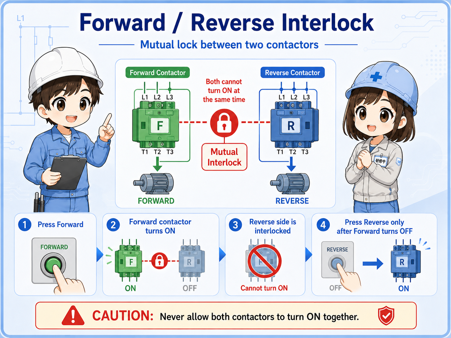
Electrical and mechanical interlocks
A real forward/reverse starter may use both electrical interlock contacts and mechanical interlock parts. Do not assume software logic alone replaces required hardware or safety design.
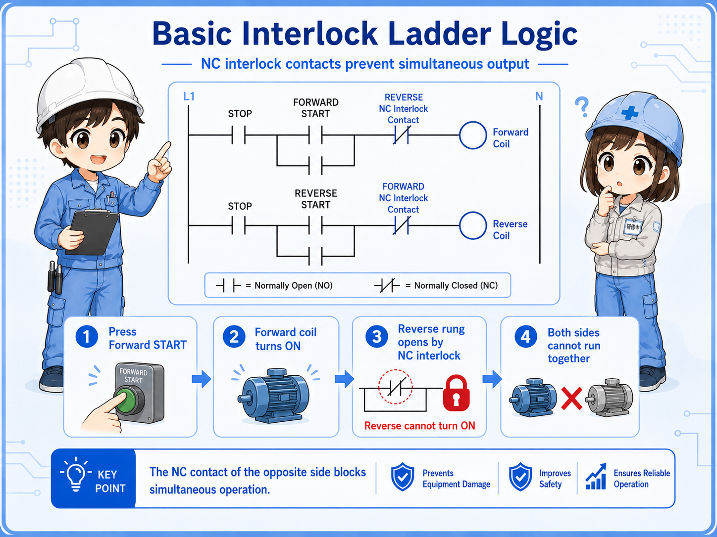
4. How interlocks appear in ladder logic
In ladder logic, an interlock often appears as a condition placed in series before the output coil.
A simple ladder-style view is that the output turns on only when its start condition is true and the opposite-side condition is not active. The interlock contact is usually read as “do not allow this output if the other side is on.”
This is a simplified learning example. In real PLC programs, interlocks may be combined with mode selection, permissive conditions, alarms, safety circuits, reset logic, self-holding circuits, and manual operation conditions.
5. Common beginner mistakes with interlocks
Interlock circuits are simple in concept, but easy to misread when several conditions are connected in series.
Thinking the output is broken
The output may be intentionally blocked by an interlock. First check whether a blocking condition is active.
Mixing up self-hold and interlock
Self-hold keeps the same output on. Interlock prevents another output or condition from turning on.
Checking only the push button
A start command can be correct, but the output may still be blocked by the opposite-side contact or PLC condition.
Ignoring hardware interlocks
PLC logic is only part of the system. Some circuits also rely on relay contacts, auxiliary contacts, and mechanical interlock parts.
Do not bypass interlocks casually
An interlock is usually there for a reason. Bypassing it without understanding the machine, drawings, and safety requirements can create dangerous movement or electrical conflict.
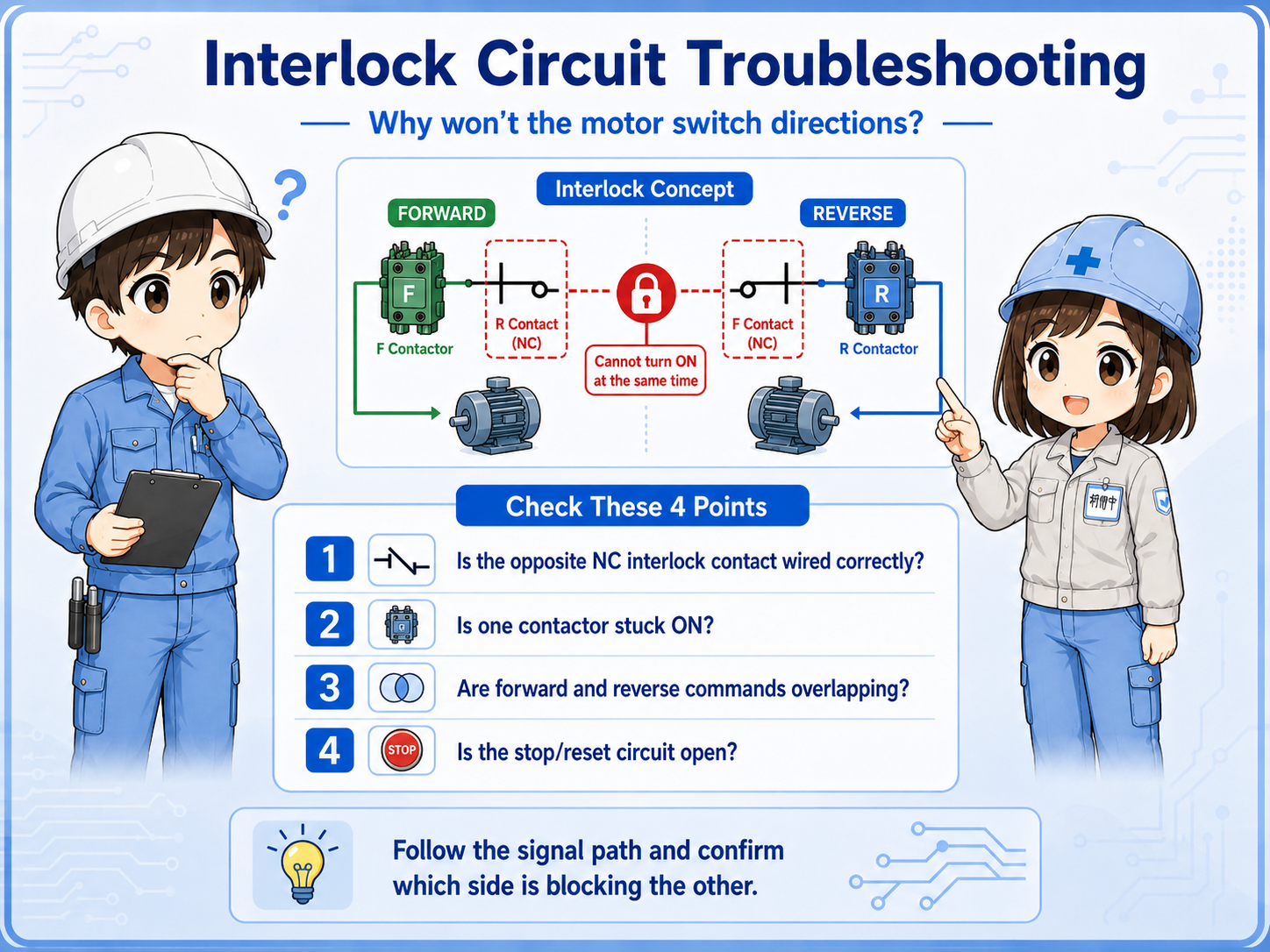
6. Troubleshooting interlock circuits
When an output will not turn on, find out whether it is missing a command or being blocked by an interlock.
Interlock troubleshooting is easier when you separate the problem into input command, interlock condition, output command, and load-side operation.
1. Check the command
Is the start button, selector switch, sensor, or PLC command actually turning on?
2. Check the blocking condition
Is the opposite-side contact, mode condition, alarm, or permissive condition preventing the output?
3. Check output status
If the command is present and the interlock is clear, does the PLC output or relay coil energize?
4. Check the field device
If the output turns on, confirm the contactor, valve, lamp, actuator, or load-side circuit is actually working.
Junior
The start button turns on, but the output does not. Does that mean the output is bad?
Senior
Not yet. First check whether an interlock is blocking the output. The circuit may be doing exactly what it was designed to do.
7. Practical safety notes
Interlocks are related to safety and equipment protection, but not every interlock is a certified safety function.
Do not treat a simple PLC interlock as a replacement for required safety circuits, safety relays, safety PLCs, guards, emergency stop circuits, or site safety procedures. Always follow the actual drawings, machine documentation, lockout/tagout rules, and applicable safety requirements.
Keep learning in layers
Interlock circuits become much easier after you understand inputs and outputs, NO/NC contacts, relays, self-holding circuits, and basic ladder reading.