1. A comparison instruction judges two values
Think of a comparison instruction as “turn this condition ON if the numeric relationship is true.”
In GX Works3 and MELSEC-style ladder programming, comparison conditions are often used to judge values such as timer current values, counter current values, data register values, and set values.
The beginner point is simple: a comparison is not the output itself. It is a condition. When the comparison is true, the ladder path is treated as ON and the next coil or instruction can operate.
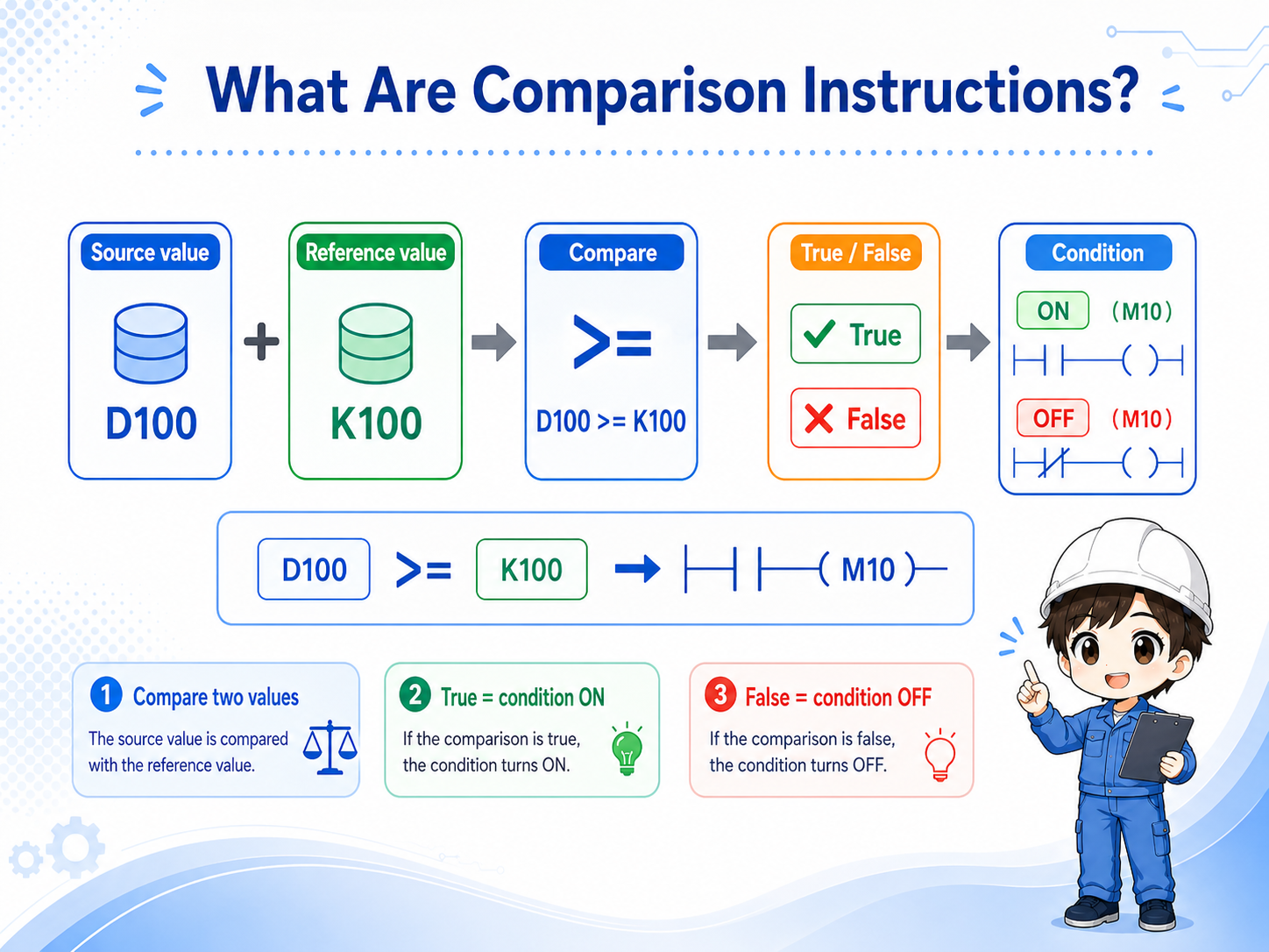

When you see a comparison, do not start by changing the symbol. First check which two values are being compared.

So I should read it like a contact that turns ON only when the value condition is true.
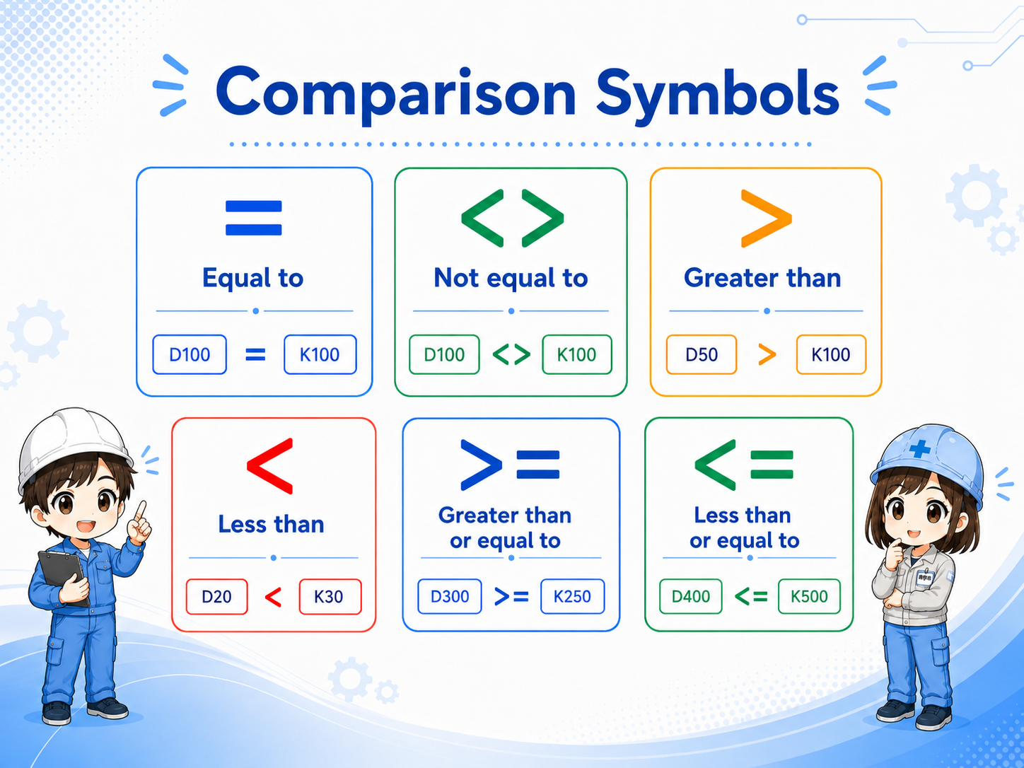
2. Read =, <>, >, <, >=, and <= slowly
Most comparison mistakes come from reversing the left side and right side, or from misunderstanding “greater than or equal to.”
Comparison symbols are simple in isolation, but they become confusing when they are buried inside a ladder program. Read the condition as a sentence: if the left value has this relationship to the right value, the condition is true.
| Symbol | How to read it | Beginner check |
|---|---|---|
| = | Left value is equal to the right value. | Useful for exact match conditions. |
| <> | Left value is not equal to the right value. | Useful when a value must be different from a reference. |
| > | Left value is greater than the right value. | Do not confuse this with greater than or equal to. |
| < | Left value is less than the right value. | Confirm which side is the monitored value. |
| >= | Left value is greater than or equal to the right value. | Often used for threshold reached conditions. |
| <= | Left value is less than or equal to the right value. | Often used for lower-limit or within-range checks. |
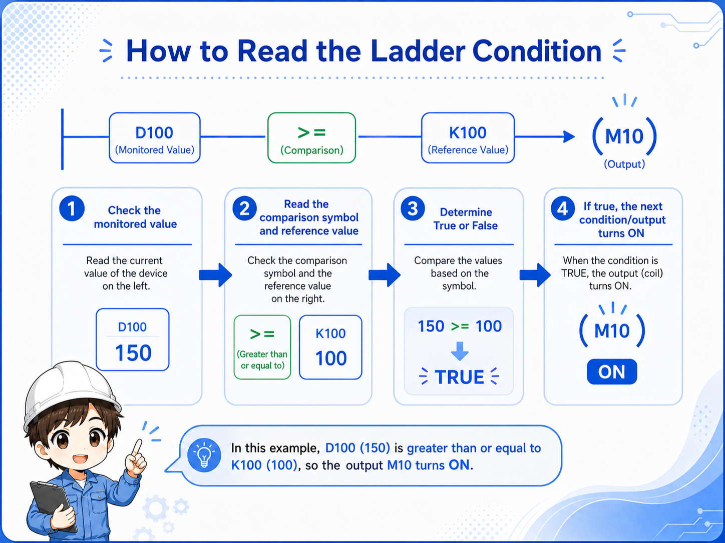
3. In ladder logic, read comparison as a condition contact
A comparison result is often easier to understand if you imagine it as a contact that turns ON only when the condition is true.
For example, a program may compare a timer current value with a set value. If the current value has reached the set value, the comparison condition turns true and the next output or instruction can operate.
This does not mean the comparison “drives the machine” by itself. It only allows the next part of the ladder program to proceed. The output coil, SET/RST instruction, or later logic still decides what happens next.
1. Read the left value
Find the actual value being monitored.
2. Read the symbol
Check whether it is equal, greater than, less than, or a range-style condition.
3. Read the right value
Confirm the set value or reference value used for comparison.
4. Common use cases: timers, counters, and data registers
Comparison instructions are often used when a numeric value decides whether the next operation should start.
You may see comparison conditions around timer current values, counter current values, production counts, analog-scaled values, or simple set values stored in data registers.
Timer value reached?
Example: continue when a timer current value is greater than or equal to a set value.
Counter target reached?
Example: stop or change state when a counter current value matches a target count.
Register value over limit?
Example: turn ON a warning when a data register value exceeds a threshold.
Value within range?
Example: allow an operation only when a value is above one limit and below another.
Keep the explanation general
Exact device ranges, instruction formats, and available comparison forms depend on the PLC series and project settings. Confirm the official manual and the machine documentation before editing a real program.
5. Common mistakes when a comparison does not turn ON
When a comparison condition does not work, the symbol is not always the cause.
In the field, many comparison problems are caused by the value itself, the unit, the timing, or another part of the ladder program. Before changing the comparison symbol, confirm the values being compared.
| Symptom | Likely check point | How to think about it |
|---|---|---|
| Condition never turns ON | The monitored value has not reached the set value. | Check the live value before changing the ladder. |
| Turns ON at an unexpected time | The unit or scale may be different. | Confirm whether the value is seconds, milliseconds, counts, or scaled data. |
| Output still does not operate | Later logic may block or overwrite the result. | Trace the ladder after the comparison condition. |
Typical field mistake
Changing > to >= without checking the actual monitored value can hide the real cause. Always check the live value, set value, and downstream condition together.
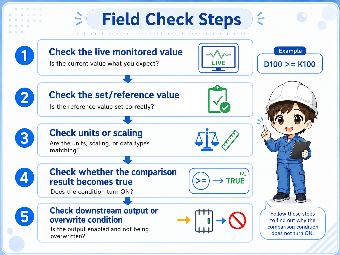
6. Field check points in GX Works3
Check comparison source, reference value, and downstream output as one set.
- Monitor the left-side value or source device.
- Confirm the right-side set value or reference device.
- Check whether the comparison result is true at the expected timing.
- Confirm whether the next coil or instruction is allowed to operate.
- Search for other rungs that overwrite the same device or output.
Field reading habit
Say the condition aloud: “If this value is greater than or equal to that value, this rung becomes true.” This helps prevent left-right mistakes.
7. Summary: comparison instructions make numeric conditions
Comparison instructions are basic but important. They turn numeric relationships into ladder conditions. Once you can read them as ON/OFF conditions, timer, counter, and register-based logic becomes much easier to follow.
- Comparison instruction judges two values.
- = / <> / > / < / >= / <= describe the relationship between left and right values.
- Field checks should include live value, set value, unit, timing, and downstream logic.
Related articles
These English articles are already available and connect well with this topic.