1. A counter instruction counts events and judges completion
Think of a counter as “count input events until the current value reaches the set value.”
In a GX Works3 ladder program, a counter is commonly used when the machine needs to count repeated events: workpieces passing a sensor, button operations, cycle counts, or alarm occurrences.
The beginner point is this: a counter is not just a number box. It has a count condition, a target value, a current value, completion contacts, and a reset condition.

When a counter does not work, do not look only at the counter number. Trace the input event and the reset condition too.

So the counter itself is only one part of the logic. I need to see what makes it count and what clears it.
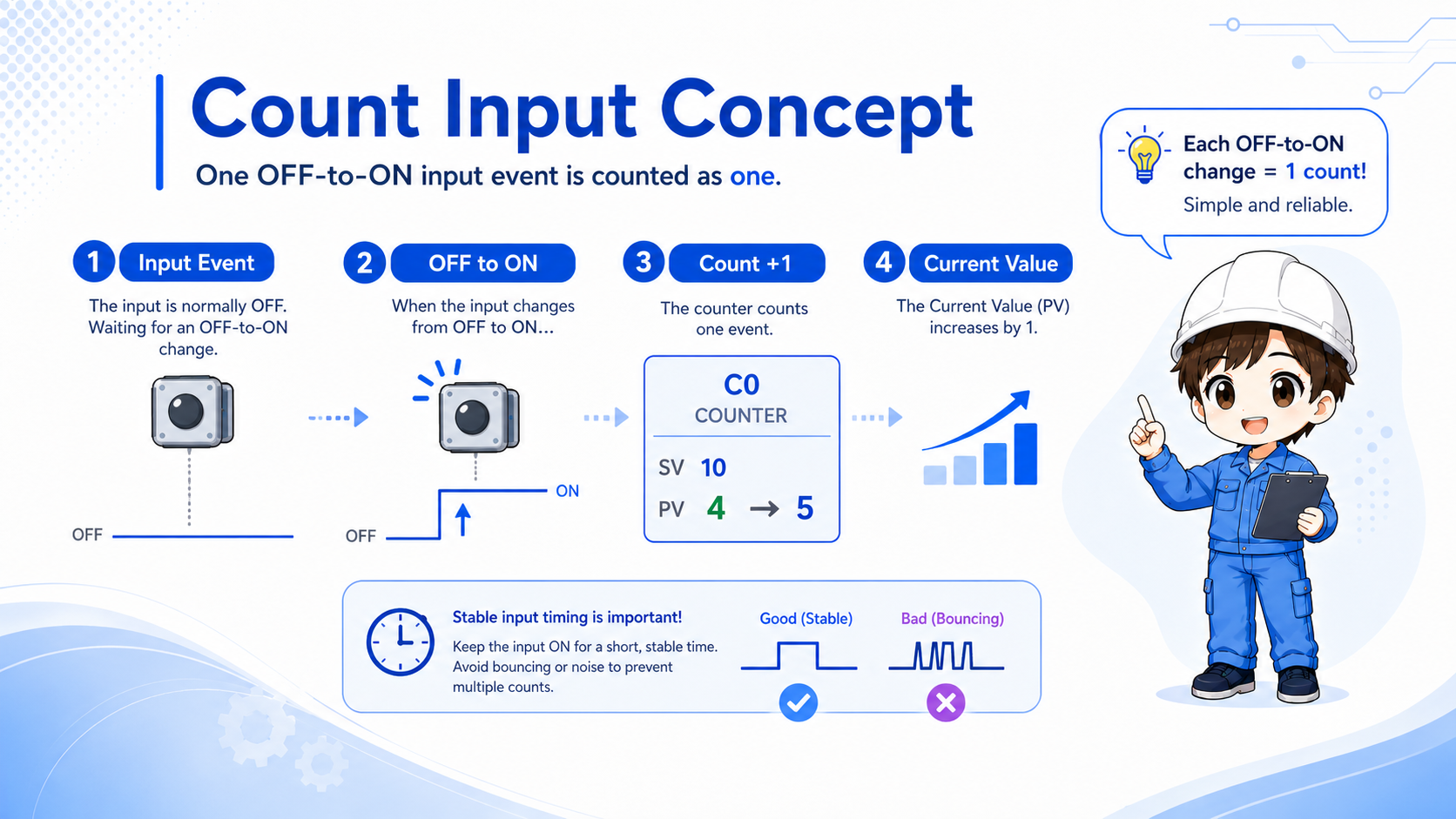
2. Count input: check the OFF-to-ON event
A normal counter should be read as counting an input event, not as continuously increasing while the input stays ON.
In practice, the important question is: what is counted as one event? A sensor turning ON, a button press, or a completed machine cycle may all be used as count inputs, but each should be clearly defined.
If a signal stays ON, it does not automatically mean the count keeps increasing every scan. For stable counting, the input condition often needs a clear change, and sometimes a one-shot style condition is used before the counter.
Field note
If a sensor stays ON for too long, the issue may not be the counter instruction. The signal timing, one-shot logic, or sensor behavior may need to be checked first.
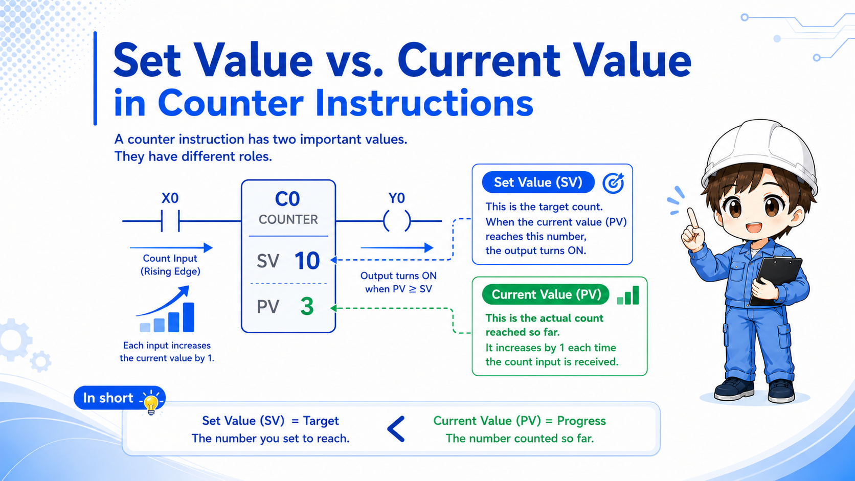
3. Set value and current value are different
The set value is the target count. The current value is the count reached so far.
Many troubleshooting mistakes happen because the set value and the current value are treated as the same thing. A set value of 10 means “completion should occur at 10.” It does not mean the counter has already reached 10.
Set value
The target number. It defines when the counter should be considered complete.
Current value
The actual count that has accumulated from count input events.
Completion
The condition that becomes true when the current value reaches the set value.
Reset
The condition that clears the current value or completed state depending on the program design.
4. Completion contacts show what happens after the target is reached
After the counter reaches the set value, its contact condition is commonly used to drive the next operation.
For example, a machine may stop, move to the next process, turn ON a lamp, or trigger another sequence when a count target is reached. The counter condition is the trigger, but downstream ladder conditions still matter.
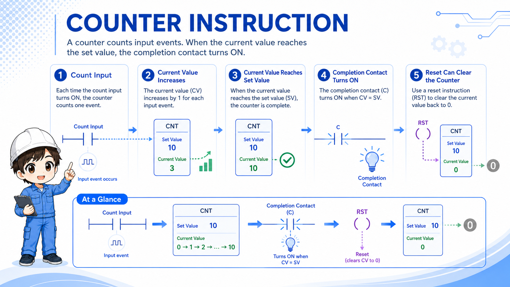
1. Count input
One event is detected.
2. Current value
The counter current value increases.
3. Completion contact
When the target is reached, the next logic can turn ON.
Do not stop at the counter
If the counter contact is ON but the output is still OFF, trace the contacts and coils after the counter condition.
5. RST reset: decide when the counter returns to zero
A counter can stay completed if the reset condition is missing, delayed, or always blocked.
The reset condition is not a small detail. It is part of the counter design. A counter often needs to be cleared when the machine starts, when an operator acknowledges completion, when a cycle ends, or when a fault recovery sequence runs.
If the reset condition is always ON, the counter may never increase. If the reset condition never turns ON, the counter may stay complete and make the next run behave unexpectedly.
When a counter acts strange after restart, check whether the current value was cleared at the right timing.
If it starts already completed, I should suspect a missing or late reset condition.
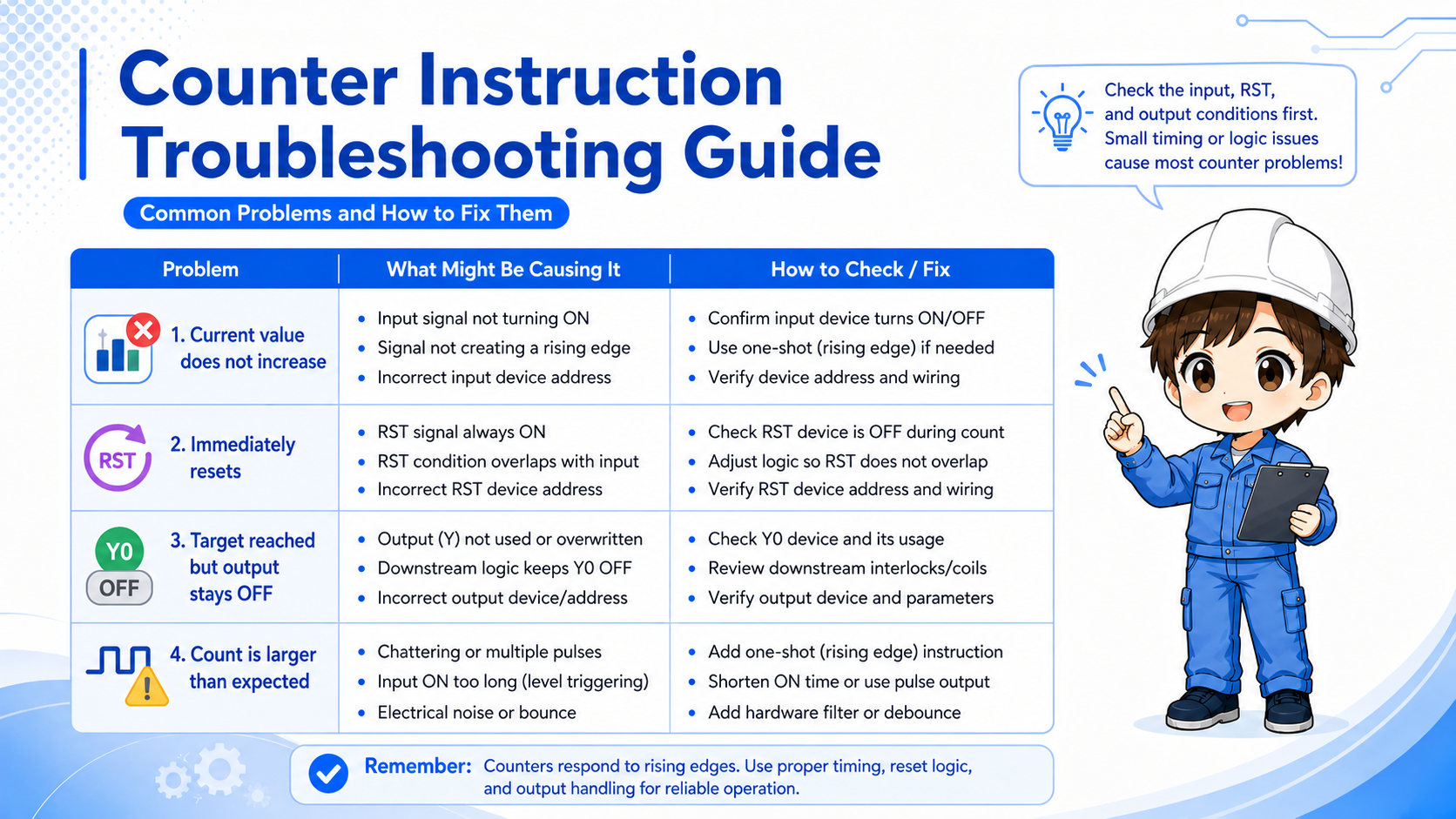
6. Common mistakes when a counter does not work
Counter problems are often caused by signal timing, reset timing, or downstream logic rather than the counter instruction itself.
| Symptom | Likely check point | How to think about it |
|---|---|---|
| Current value does not increase | The count input may not have a clear OFF-to-ON event. | Monitor the input condition and scan timing. |
| Counter immediately resets | RST condition may be ON at the same time. | Check whether reset logic is blocking counting. |
| Counter reaches target but output does not turn ON | Downstream contacts may be OFF. | Trace the ladder after the counter contact. |
| Count is larger than expected | Chattering or repeated pulses may be counted. | Check sensor stability, filtering, and one-shot logic. |
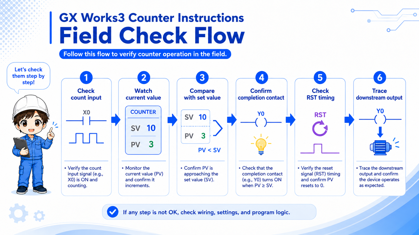
7. Field check points in GX Works3
Monitor at least four points together: count input, current value, completion contact, and reset condition.
- Check whether the count input turns OFF and ON at the expected timing.
- Watch whether the current value increases by one for each intended event.
- Compare the current value with the set value.
- Confirm whether the completion contact turns ON when the target is reached.
- Check whether RST is ON too early, never ON, or triggered by another rung.
- Trace the output or next sequence after the counter condition.
Important
Exact counter devices, ranges, and instruction details depend on the PLC series and project settings. Confirm the official manual and the machine documentation before editing a real program.
8. Summary: counter instructions are easier when you check the whole group
A counter instruction becomes much easier to read when you separate the count input, set value, current value, completion contact, and reset condition. In troubleshooting, check them together instead of changing only the counter symbol or set value.
- Count input defines what is counted as one event.
- Set value is the target; current value is the actual count so far.
- RST must be designed and checked as part of the counter behavior.
Related articles
These English articles are already available and connect well with this topic.