1. The basic idea: information comes in, commands go out
Start with the direction of the signal. That is the easiest way to understand inputs and outputs.
In electrical control, an input is a signal that comes into the controller. It reports a condition, a detection signal, or an operator action. An output is a signal that goes out from the controller. It drives a device or gives equipment a command.
Short version: inputs report. Outputs operate.
A push button, selector switch, sensor, or limit switch is usually treated as an input device. A pilot light, buzzer, solenoid valve coil, relay coil, or contactor coil is usually treated as an output device.
- Input signal
- Output command
- Field device
- PLC I/O
The easiest way to remember it
Inputs tell the controller what is happening. Outputs tell equipment what to do. This simple idea is the foundation for reading I/O lists, wiring diagrams, and ladder logic.

Senior
When you are not sure, start with the direction. Is the signal coming into the PLC, or is the PLC sending a command out?

Junior
So a sensor signal coming into the PLC is an input, and a lamp command going out is an output?
Senior
Exactly. Once you understand that, troubleshooting becomes much easier.
2. Common input and output devices in real work
Device names are useful, but the signal direction matters more than the name.
Beginners often learn faster when the idea is connected to real devices. If a device reports a condition or operator action, it is usually an input. If a device is energized, driven, or commanded by the controller, it is usually an output.
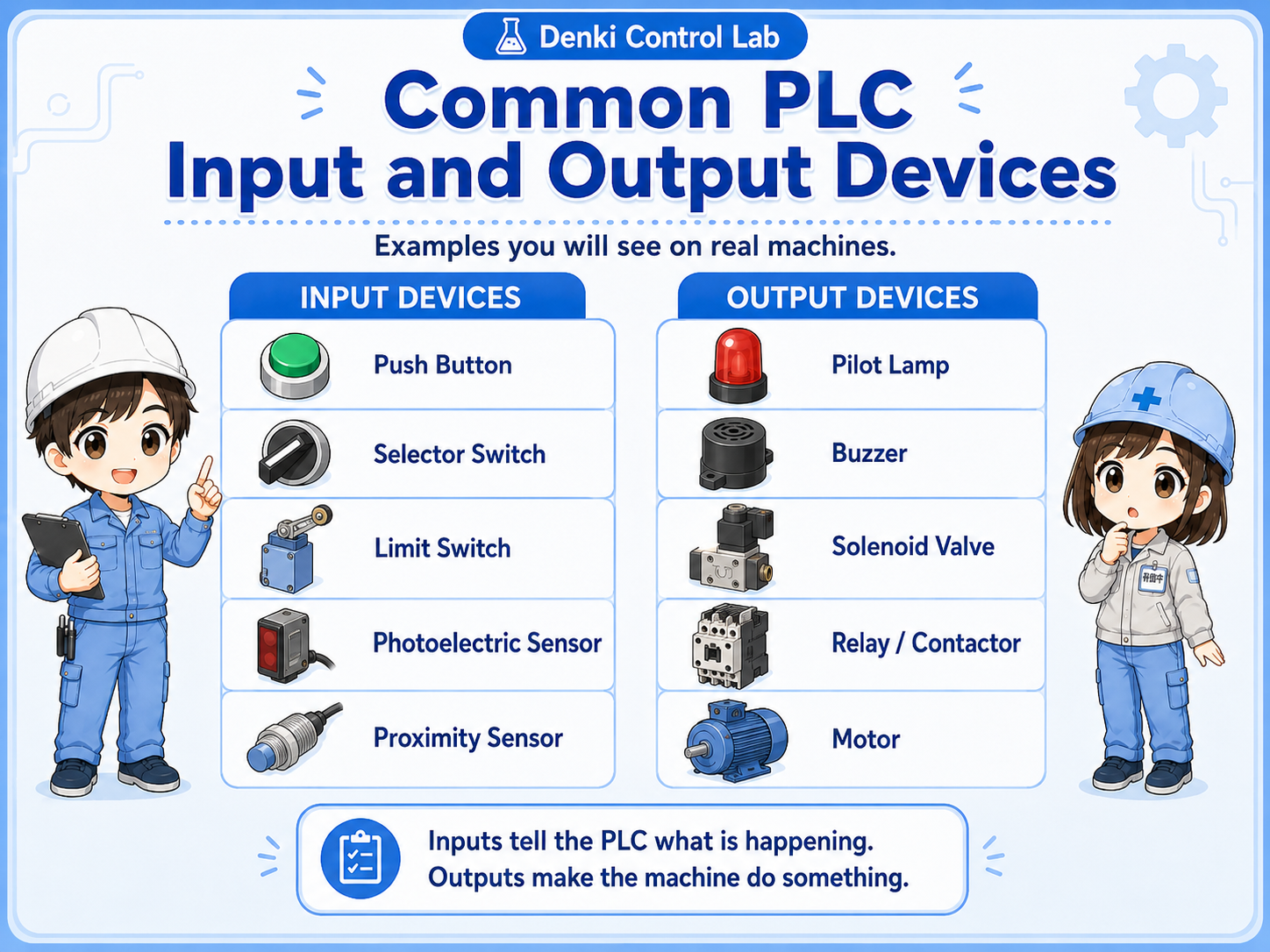
| Type | Typical devices | What they do |
|---|---|---|
| Input | Push button, selector switch, sensor, limit switch, auxiliary contact | Report a status, detection, position, or operator action to the controller. |
| Output | Pilot light, buzzer, solenoid valve coil, relay coil, contactor coil | Receive a command from the controller and drive equipment or indicators. |
| Depends on use | Relay, contactor, feedback contact, auxiliary contact | A coil can be an output, while a contact from the same device can become an input signal elsewhere. |
Field-friendly rule
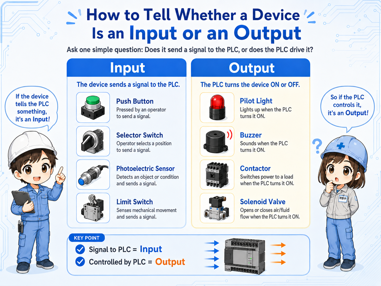
If the device is telling the PLC something, think input. If the PLC is turning the device on or off, think output.
3. How PLC inputs and outputs are usually labeled
Many PLC projects separate inputs and outputs by device labels or address areas.
In many Mitsubishi PLC projects, X is commonly used for inputs and Y is commonly used for outputs. For example, X0 may be a start button input, while Y0 may be a pilot light or output coil.
Check the actual project
The exact numbering depends on the PLC model, I/O module, project design, and site standard. Always confirm with the actual drawings, I/O list, and PLC program.
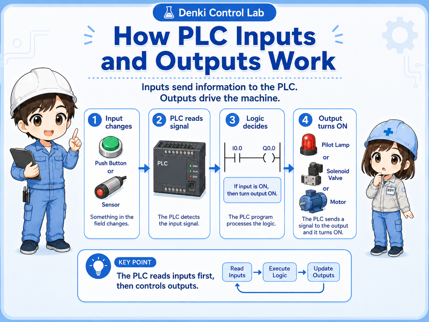
Input device
A push button, sensor, or switch changes state in the field.
PLC input
The PLC reads the signal, often shown as an input address such as X0 or X1.
PLC output
The program turns on an output address such as Y0 or Y1 to drive a device.
4. How to tell whether a device is an input or an output
Ask one question: is it reporting a condition, or is it receiving a command?
When you look inside a control panel, it is easy to get confused. The best starting point is to ask whether the device is sending information to the controller or receiving a command from the controller.
Usually an input
Push buttons, sensors, limit switches, selector switch contacts, and feedback contacts usually report information to the controller.
Usually an output
Pilot lights, buzzers, solenoid valve coils, relay coils, and contactor coils usually receive commands from the controller.
Do not judge only by name
A relay coil may be an output, but an auxiliary contact from that relay may be used as an input signal.
Follow the drawing
The I/O list, terminal numbers, and wiring diagram are more reliable than guessing from the device name alone.
Junior
I always get confused when I see many wires and devices inside a panel.
Senior
Look at the role first. Is it reporting a condition, or is the controller driving it? That question usually gives you the answer.
5. Common beginner mistakes
The confusing part is often not the word “input” or “output,” but how a device is used in the circuit.
A common mistake is thinking that one physical device always belongs to only one side. In real control panels, a device can have a coil, contacts, feedback, and wiring that serve different roles.
Watch for these mistakes
Do not assume every field device is an output. Do not assume a relay is always one thing. A relay coil may be driven by a PLC output, while its auxiliary contact may report status back as an input.
- Mixing up the device body, the coil, and the contact.
- Looking only at the device name instead of the signal direction.
- Misreading X and Y when checking a PLC I/O list.
- Forgetting that feedback contacts can become input signals.
6. Using inputs and outputs for troubleshooting
Separating input-side checks from output-side checks helps you avoid chasing the wrong problem.
If a machine does not operate, first ask whether the controller is receiving the expected input. Then ask whether the controller is sending the expected output. This separates the problem into an input-side issue, a logic issue, or an output-side issue.
Input-side check
Is the switch, sensor, or limit switch actually turning on? Is the PLC input status changing?
Program-side check
Does the ladder logic allow the output to turn on? Are interlocks, modes, or reset conditions blocking it?
Output-side check
Is the PLC output turning on? Is the relay, lamp, valve, contactor, or load-side power circuit working?
Field check
Use the drawings, I/O monitor, terminal numbers, and a safe measurement method. Do not guess only from the symptom.
Field-friendly troubleshooting flow
Input status correct? → Logic condition satisfied? → Output status on? → Load actually operating? This order keeps the troubleshooting path clear.
7. Practical safety notes
Input and output basics help you read a circuit, but they do not replace safe work procedures.
Control wiring and PLC troubleshooting must follow your site rules, drawings, lockout/tagout procedures, and applicable safety requirements. A PLC output may turn a device on unexpectedly if the program condition changes, so always confirm the machine state before testing.
Keep learning in layers
First understand input and output direction. Then study NO/NC contacts, sensors, relays, self-holding circuits, interlocks, and safety circuits one at a time.