1. What a self-holding circuit does
First, only remember one thing: the circuit keeps itself on after the start button is released.
A self-holding circuit is a basic control pattern that keeps an output on after a momentary start signal has been removed. In other words, you press the start pushbutton once, the output turns on, and the circuit continues running even after you take your finger off the button.
Short version: the start button gives the first command, and then another path takes over so the output can keep running.
This idea appears in both hardwired relay control and PLC ladder logic. The symbols or software screens may look different, but the logic is the same: the circuit creates a holding path that keeps the output energized.
- Start pushbutton
- Holding contact
- Output coil
- Stop pushbutton
Think of it as a “memory” pattern
The circuit “remembers” that the start command was given. That does not mean advanced memory logic is required. It simply means the output creates a path that keeps itself energized until another condition, usually the stop button, breaks the path.

Senior
The most common beginner mistake is thinking the start button stays “active.” It does not. The output stays on because the holding contact closes after the output turns on.

Junior
So if the output only stays on while I keep pressing START, I should first check whether the holding path is actually being made, right?
2. Why the circuit stays on after the start button is released
This section is the core idea of the whole article.
The start pushbutton is usually a normally open contact. When the button is not pressed, the contact is open. When you press it, the contact closes and allows the output coil to energize.
The important part is that the output also has its own normally open auxiliary contact, often called a holding contact or seal-in contact. This contact is placed in parallel with the start pushbutton.
| Part | Typical English term | Role in the circuit |
|---|---|---|
| Start button | Start pushbutton / normally open contact | Provides the first command that energizes the output coil. |
| Output contact | Holding contact / seal-in contact | Creates a parallel path so the coil can stay energized after the start button opens again. |
| Output coil | Output coil / relay coil / PLC output | Turns on the load or command, and closes the holding contact linked to that output. |
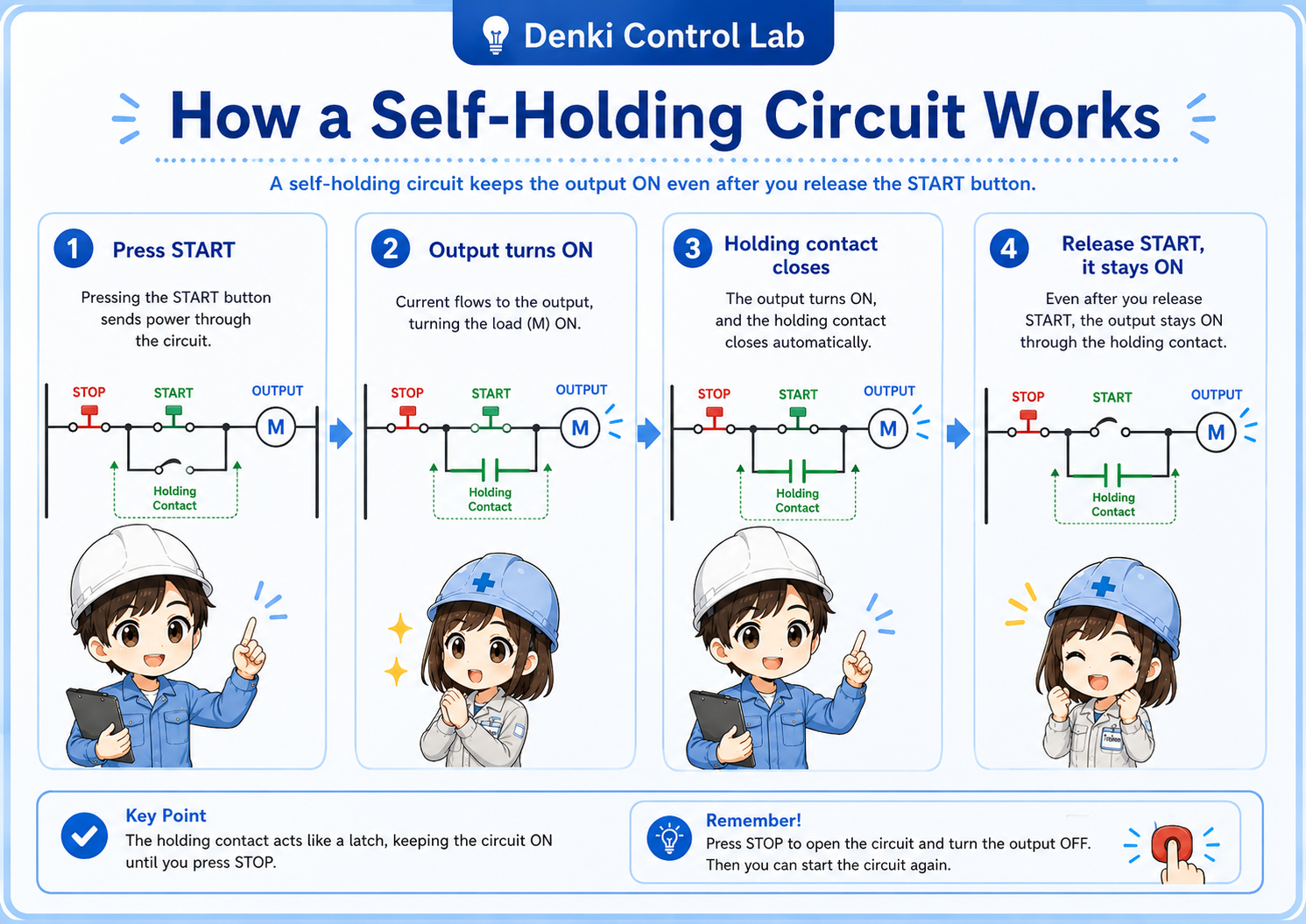
1. Press START
The start contact closes for a moment.
2. Output turns ON
The coil energizes and changes state.
3. Holding contact closes
A parallel path is now available.
4. Release START
The output stays on through the holding path.
The one sentence to remember
Press start → the output coil turns on → the holding contact closes → release start → the holding contact keeps the circuit on.
Senior
If you understand this sequence, you already understand most basic self-holding circuits. Everything else is usually just extra conditions added around the same idea.
3. How the stop button breaks the holding path
Start makes the circuit run. Stop breaks the path and resets the circuit.
A basic self-holding circuit also needs a clear way to turn off. That is the role of the stop pushbutton. In a typical start/stop control circuit, the stop pushbutton is treated as a normally closed contact in the control path.
Important reading point: a normally closed stop contact is closed during normal operation and opens when the stop button is pressed.
When the stop button is not pressed, the contact remains closed and the circuit can operate. When the stop button is pressed, that path opens. The output coil drops out, and once the output turns off, the holding contact opens as well.
Do not confuse “pressed” with “contact state”
A normally closed stop contact is closed during normal operation and opens when the stop button is pressed. This is one reason beginners sometimes get confused when reading ladder logic or wiring diagrams.
Junior
I see. So the “normal” state of the stop contact is closed, even though pressing STOP makes it open.
Senior
Exactly. That is why you should not rely only on the label. Always think about the actual contact state during operation.
4. Basic ladder logic example
You do not need perfect ladder notation to understand the logic. Follow the path from left to right.
A common ladder-style self-holding rung can be described like this:
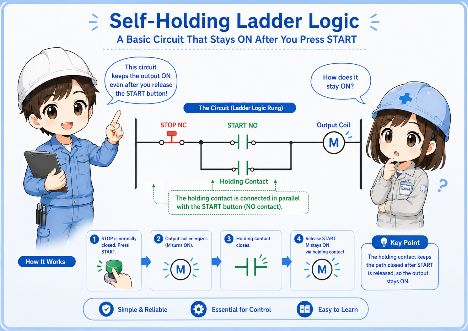
When START is pressed
The start contact closes, the rung becomes true, and the output coil turns on.
After START is released
The start contact opens again, but the holding contact is now closed, so the output remains on.
When STOP is pressed
The stop contact opens, the rung becomes false, and the output coil turns off.
After the output turns off
The holding contact opens too, so the circuit is reset and waits for the next start command.
In Mitsubishi PLC work, you may see this idea expressed with devices, labels, contacts, and coils inside ladder logic. The exact addresses and symbols depend on the project, but the reasoning is still the same: a contact linked to the output provides the self-holding path.
5. Relay wiring and PLC ladder logic use the same idea
Different hardware, same control logic.
A self-holding circuit can be built with physical relays, or it can be written as PLC ladder logic. The hardware may be different, but the logic pattern is very similar.
| Viewpoint | Hardwired relay circuit | PLC ladder logic |
|---|---|---|
| Holding path | Made with an auxiliary relay contact. | Made with a contact instruction linked to an output or internal bit. |
| Output | Relay coil, magnetic contactor coil, or lamp circuit. | Output coil, internal relay, or control bit in the program. |
| Troubleshooting | Check wiring, contact state, coil voltage, and terminal connections. | Check input status, device state, duplicate coils, interlocks, and reset logic. |
Senior
If you already understand relay contacts and coils, PLC ladder logic becomes much easier. You can still read it as a path made of contacts and coils.
6. What to check when the circuit does not stay on
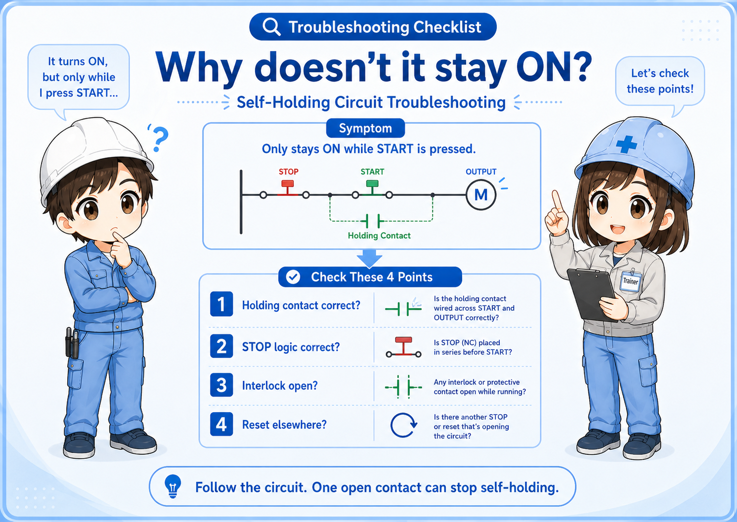
If it only stays on while you keep pressing START, think “holding path” first.
If the circuit turns on only while the start button is pressed, the holding path is probably not being completed. The cause may be wiring, device assignment, ladder logic, or another condition that is opening the rung.
1. Is the holding contact linked to the correct output?
The holding contact should follow the same output coil or control bit that you expect to hold. If the wrong device is used, the circuit will not latch.
2. Is the holding contact placed in parallel with START?
If the holding contact is placed in the wrong series position, it may not create a bypass path around the start pushbutton.
3. Is the STOP contact logic correct?
A normally closed stop contact is a common source of confusion. Check the actual input state and the ladder instruction state, not just the button name.
4. Is another interlock opening the rung?
Overload contacts, safety-related conditions, limit switches, permissive signals, and alarm bits may all prevent the output from staying on.
5. Is the same output being reset somewhere else?
In PLC programs, another rung, reset instruction, function block, or sequence step may turn the same output off.
6. Are you watching the live status?
During troubleshooting, monitor the actual input and output states. A drawing alone may not show a broken wire, failed contact, or unexpected field condition.
Field-friendly way to read it
Do not start by memorizing symbols. Follow the path: stop condition closed → start or holding path closed → output coil energized. If one part of that path is open, the circuit will not stay on.
7. Practical safety notes
A self-holding circuit explains the control idea, but it is not a full safety design by itself.
A self-holding circuit is a basic control pattern, not a complete safety design. It can explain why a machine keeps running, but it does not replace proper safety circuits, emergency stop design, risk assessment, lockout/tagout procedures, or site-specific rules.
Do not use this article as wiring approval
Actual machine wiring and PLC changes must follow your site specifications, local regulations, applicable standards, and the judgment of qualified personnel. Always verify the machine state safely before testing or changing control logic.
In real equipment, the self-holding rung may also include permissive contacts, overload contacts, door switch status, auto/manual mode conditions, or safety relay outputs. For learning, it is best to understand the simple version first, then add each real-world condition one at a time.