What is an inverter?
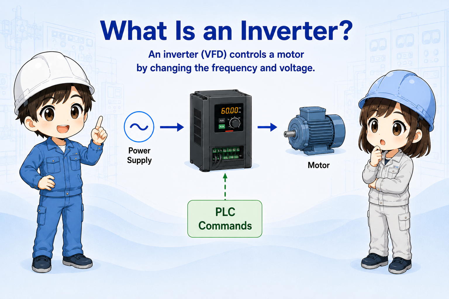
An inverter controls a motor by changing the frequency and voltage supplied to the motor.
In a control panel, an inverter is usually installed between the power supply and the motor. Instead of simply turning the motor ON and OFF, it can control how fast the motor rotates.
This is useful when a machine needs soft starting, speed adjustment, acceleration and deceleration control, or speed commands from a PLC.

An inverter is used when you want more than just ON/OFF motor control. It lets the motor start gently, stop gently, and run at different speeds.

So if the motor does not run, I should not only check the motor. I need to check the inverter command, alarm, wiring, and parameters too.
Always confirm the actual model manual
Terminal names, parameter numbers, wiring methods, braking options, communication settings, and safety functions differ by manufacturer and model. Use the official manual for the actual inverter.
Frequency and motor speed
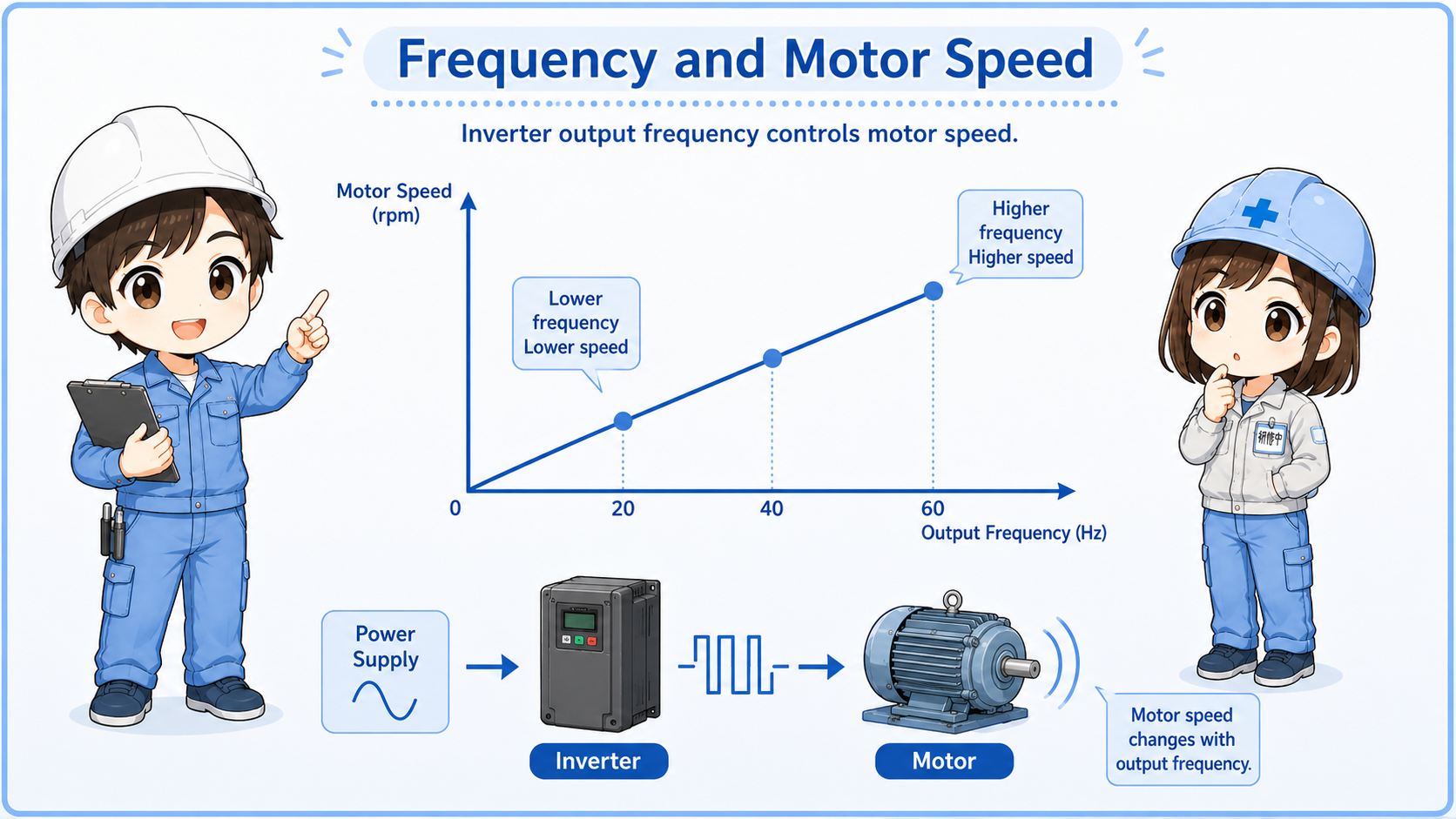
For many AC motors, changing frequency changes the rotation speed.
A common way to understand an inverter is: higher frequency generally means higher motor speed, and lower frequency generally means lower motor speed.
The inverter also controls acceleration and deceleration, so the motor does not have to start or stop suddenly.
| Term | Basic meaning | Field image |
|---|---|---|
| Frequency | The output frequency sent from the inverter to the motor. | Often shown in Hz on the inverter display. |
| Acceleration time | How long the motor takes to speed up. | Used to avoid sudden starts or excessive shock. |
| Deceleration time | How long the motor takes to slow down. | Too short a deceleration time can cause overvoltage alarms depending on the system. |
How a PLC commands an inverter
A PLC may command run/stop, direction, speed, or other functions depending on the system.
The command method can be simple digital inputs, analog voltage/current, or communication. For example, a PLC may turn ON a run signal and send a speed reference through an analog output or network.
1. Run command
The PLC tells the inverter to run or stop.
2. Speed command
The PLC or panel sets the target frequency or speed.
3. Motor output
The inverter outputs controlled power to the motor.
Command source matters
If the inverter is set to panel operation, PLC commands may not work. If it is set to terminal or communication operation, the panel buttons may not work as expected.
Basic wiring checks
Inverter wiring includes main power, motor output, control inputs, speed command, and grounding.
Before changing settings, confirm the wiring path. The inverter has a power side, a motor side, and a control side. Mixing these up can lead to dangerous or damaging mistakes.
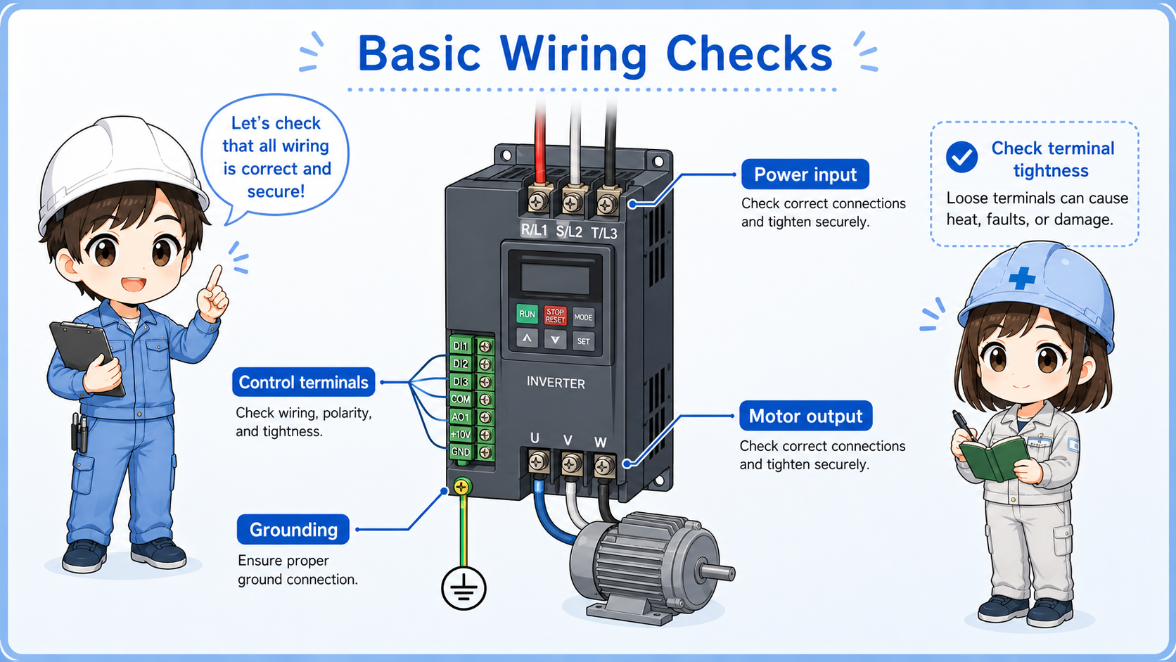
Power input
Confirm the correct supply voltage, phase, breaker, and incoming power condition.
Motor output
Check motor wiring, terminal looseness, and whether the motor matches the inverter application.
Control terminals
Check run command, direction command, common wiring, and input logic.
Speed reference
Confirm analog command, communication command, or keypad setting source.
Grounding and noise
Check grounding, shield treatment, and separation from weak signal wiring.
Alarm output
Confirm fault output, reset input, and how the PLC receives alarm status.
Do not touch live inverter terminals casually
Inverters can contain dangerous voltages and stored charge. Follow site safety rules, wait for discharge time, and confirm the official manual before working on wiring.
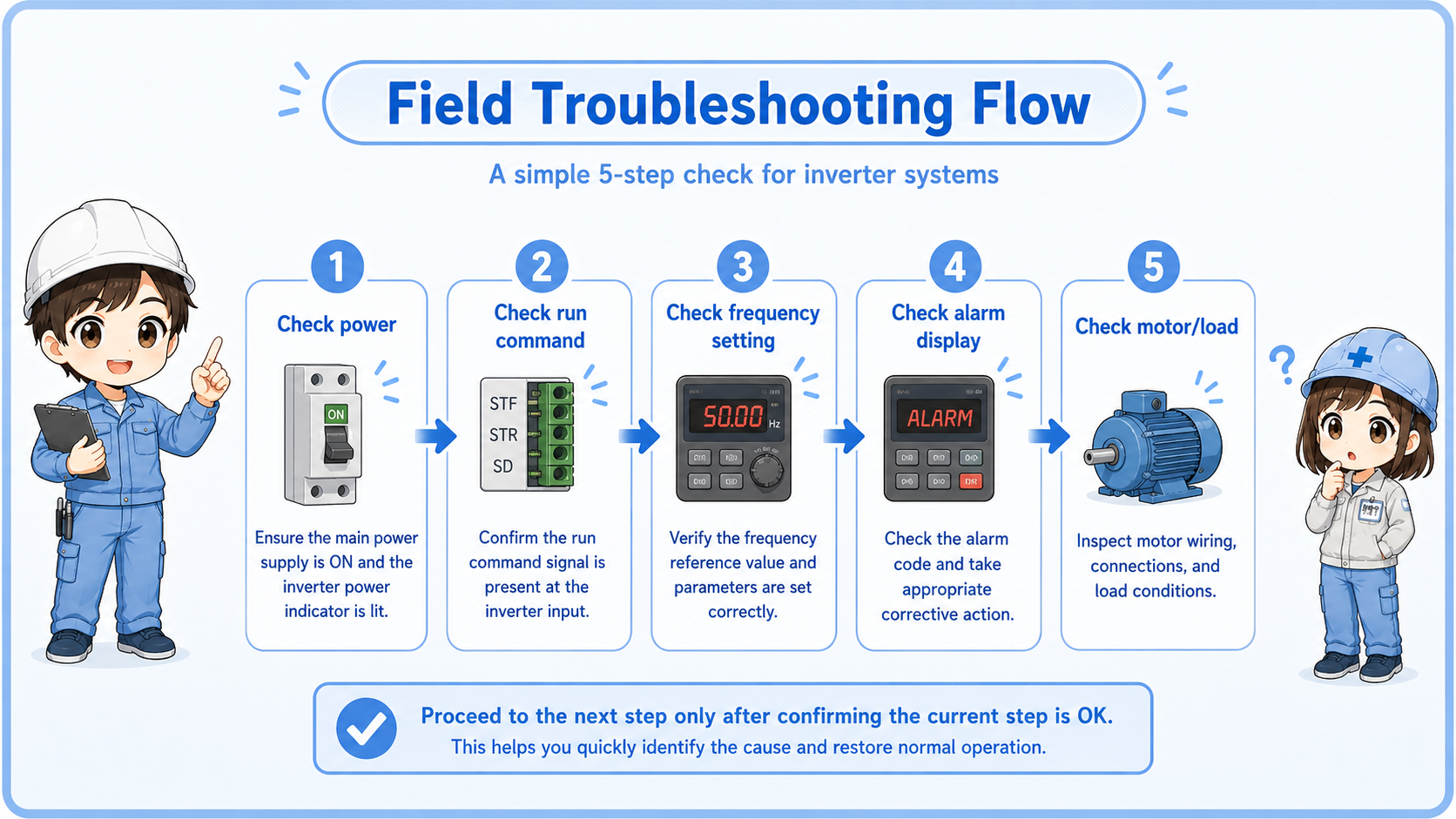
Field troubleshooting when a motor does not run
Check command, status, alarm, frequency, wiring, and the motor side in order.
| Symptom | Possible area | First check |
|---|---|---|
| Inverter display is OFF | Power supply, breaker, input wiring, control power. | Check incoming power and protection devices. |
| Display is ON but motor does not run | Run command, command source, interlock, alarm, parameter setting. | Check run command status and command source setting. |
| Motor runs at wrong speed | Frequency command, analog signal, communication setting, limit setting. | Check displayed frequency and speed reference source. |
| Alarm occurs during acceleration or deceleration | Load, acceleration time, deceleration time, motor condition, braking condition. | Check alarm code and related manual explanation. |
Record the status before changing settings
Write down the displayed frequency, command source, alarm code, and key parameters before changing anything. This makes it easier to return to the original condition.
Summary
An inverter controls motor speed by changing the output frequency. It is used when a motor needs speed adjustment, soft starting, controlled stopping, or commands from a PLC.
In the field, do not judge the motor or inverter from one symptom. Check power, command source, run command, speed reference, alarm code, wiring, parameters, and machine load in order.
Final takeaway
An inverter is the control point between the electrical command and the motor. Troubleshooting works best when you separate command, inverter status, wiring, and motor-side conditions.
Related articles
Read these next to connect inverter basics with motor switching, PLC I/O checks, and control signal fundamentals.