Good fit for
- Beginners who see DC motors, drivers, or small actuators in equipment
- Electricians learning how output signals become motor motion
- People who want to separate ON/OFF, direction, and speed control
A DC motor turns when DC power is applied, but real equipment usually needs a motor driver, control signals, wiring protection, and feedback. This guide explains the basic control patterns before you design or troubleshoot a circuit.
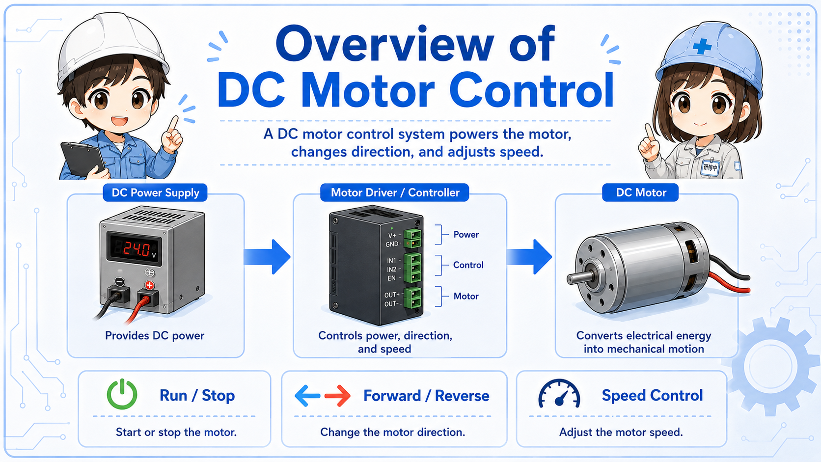
DC motor control means controlling when the motor runs, which direction it turns, and how fast it rotates.
A DC motor rotates when direct-current power is applied. In simple equipment, it may be switched ON and OFF directly. In practical control systems, however, a motor driver is commonly used between the control signal and the motor.
The driver receives commands such as run, stop, direction, or speed reference. It then applies the proper voltage and current to the motor. This separation is important because a PLC output or small switch is usually not meant to drive the motor current directly.
The PLC or switch gives an instruction. The motor driver handles the motor power. The DC motor moves as a result.
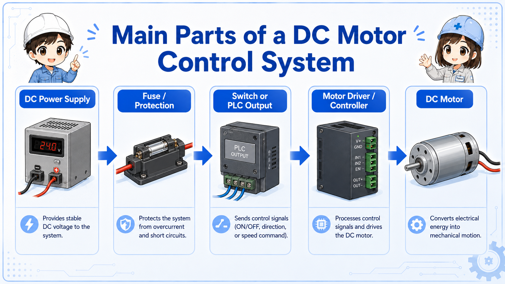
A DC motor circuit is easier to read when you separate power, driver, signal, and motor.
Many beginner mistakes come from mixing up the signal circuit and the motor power circuit. The command signal may be only a small ON/OFF or analog reference, while the motor side carries the current that actually drives the load.
Provides the voltage and current used by the motor and driver.
Controls output to the motor based on command signals.
Converts electrical power into rotation or mechanical motion.
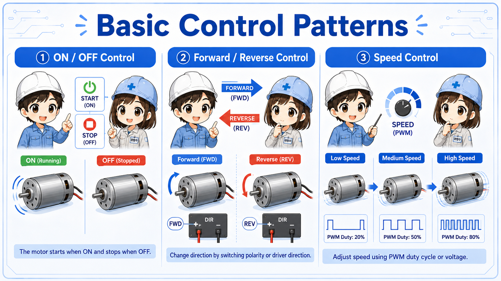
The control method changes depending on what the machine needs the motor to do.
ON/OFF control is the simplest idea: the motor runs or stops. Forward/reverse control changes the rotation direction. Speed control adjusts how fast the motor rotates, often through a driver setting or speed reference signal.
| Control type | What it does | Beginner viewpoint |
|---|---|---|
| ON/OFF control | Runs or stops the motor | Start with the run signal, driver enable, and power supply |
| Forward/reverse control | Changes the motor rotation direction | Check direction input, polarity control, and interlock logic |
| Speed control | Adjusts motor speed | Check the driver setting, speed command, and load condition |
Forward/reverse control may require stop timing, interlock, braking, or driver-specific conditions. Always check the machine drawing and driver manual.
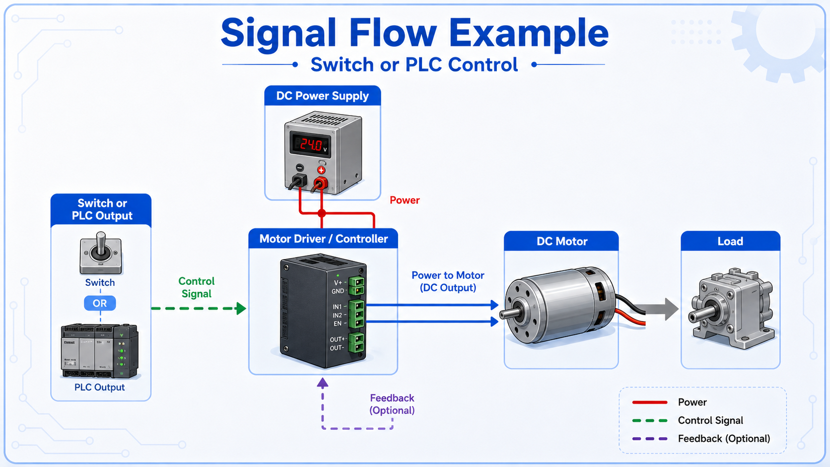
Troubleshooting becomes easier when you trace the command and power flow separately.
A simple control chain may be: PLC output or switch contact → motor driver input → driver output → DC motor rotation. If the system includes speed control, there may also be a speed reference, setting dial, analog input, or communication signal.
When the motor does not run, do not check only the motor. Check whether the command reached the driver, whether the driver is ready, whether power is present, and whether the motor or load is mechanically blocked.
A driver can receive a command but still not rotate the motor if it is disabled, faulted, missing power, overloaded, or blocked by the load.
A short conversation helps separate the signal side from the power side.

When a DC motor does not run, do not jump straight to replacing the motor. First check whether the driver has power, whether it is ready, and whether the run command is reaching the input.

So even if the PLC output is ON, the motor may not move because the driver or power side has a problem?
Exactly. Check the command, driver status, motor output, wiring, and mechanical load in order.
A motor problem can come from the signal side, power side, driver, motor, wiring, or mechanical load.
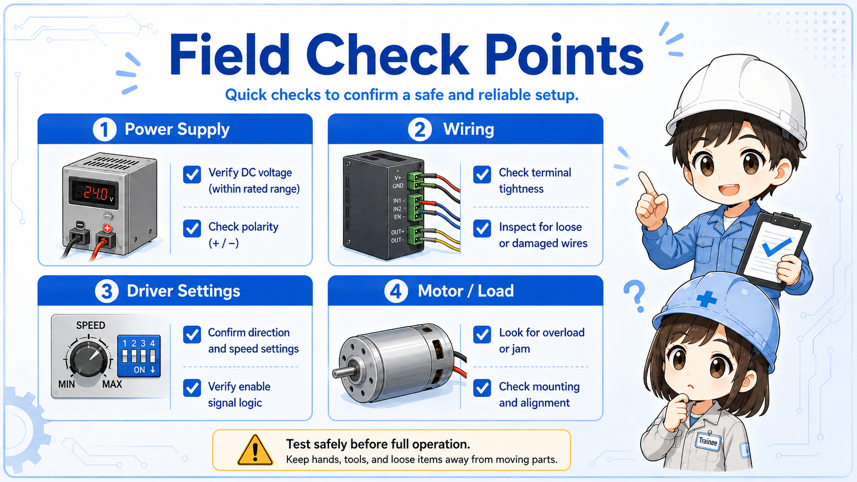
Check DC supply voltage, polarity, fuse, breaker, terminal looseness, and driver power input.
Check PLC output, switch contact, input common, direction input, enable input, and speed reference.
Check alarm, fault, enable state, setting switches, protective functions, and manual reset conditions.
Check motor wiring, connector, rotation direction, load jam, gear mechanism, belt, and mechanical resistance.
For real equipment, always confirm the driver manual. Terminal names, input logic, alarm behavior, braking, and speed reference methods differ by model.