1. The basic idea: which side does the sensor switch?
NPN and PNP are easiest to understand by looking at the side of the DC24V circuit that is being switched.
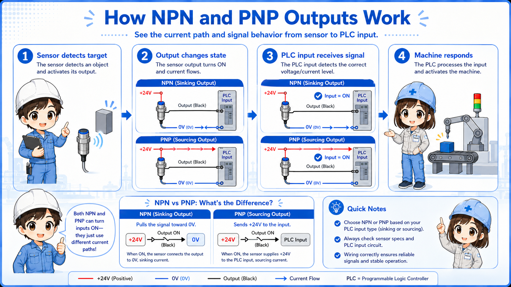
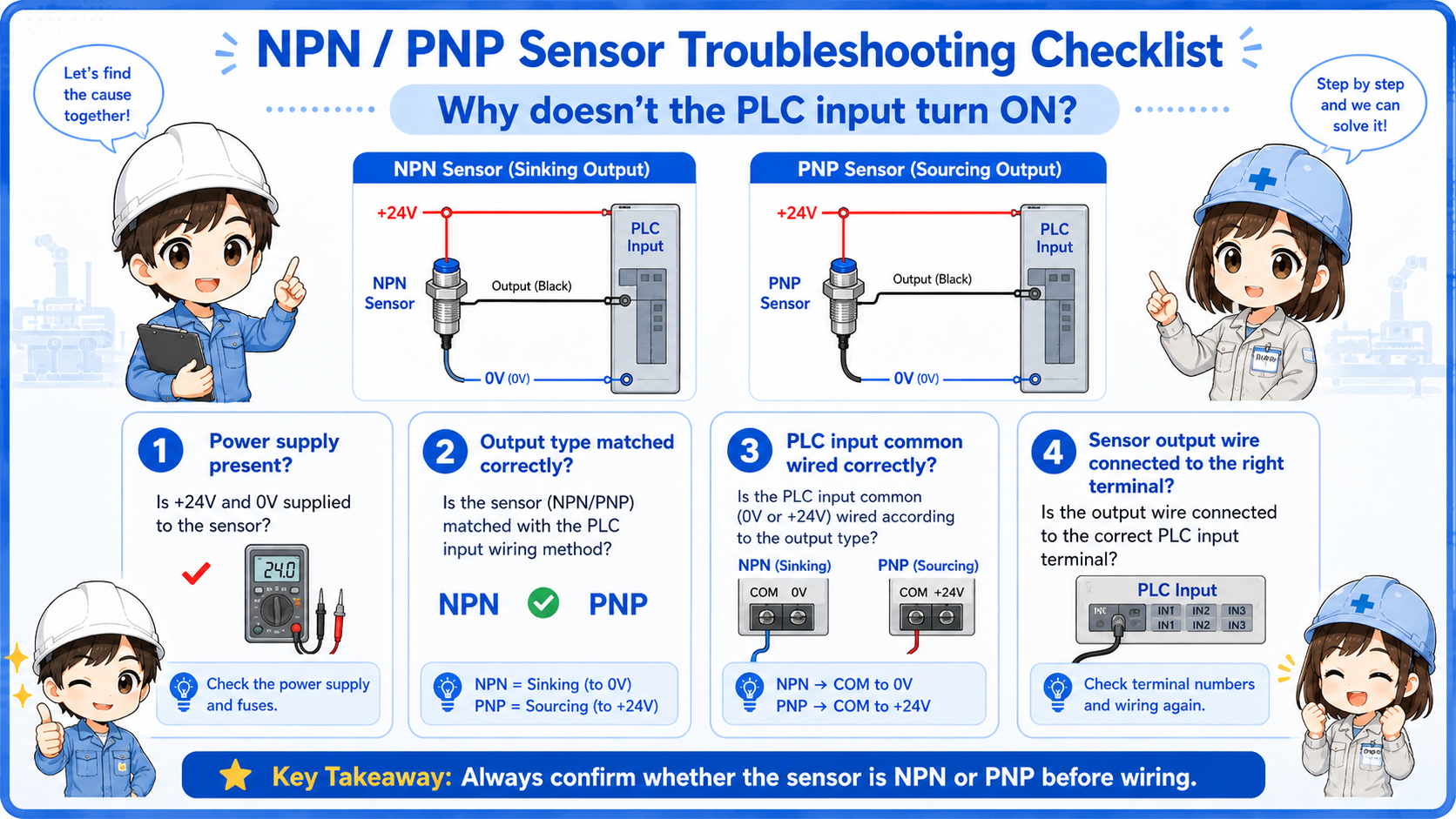
In a typical DC24V sensor circuit, the PLC input turns on when the correct current path is created. An NPN sensor creates that path by switching the 0V side. A PNP sensor creates that path by switching the +24V side.
Short version: NPN pulls the signal toward 0V. PNP pushes +24V to the input.
- NPN
- PNP
- Sinking
- Sourcing
- 0V switching
- +24V switching
The first question to ask
Do not start by asking only “is the sensor ON?” Ask “when the sensor is ON, does the output provide +24V or connect to 0V?”

Senior
If the sensor LED is on but the PLC input is off, NPN/PNP mismatch is one of the first things to suspect.

Junior
So the sensor can be working, but the PLC input still may not receive the correct signal?
Senior
Exactly. The output type and input unit wiring must match.
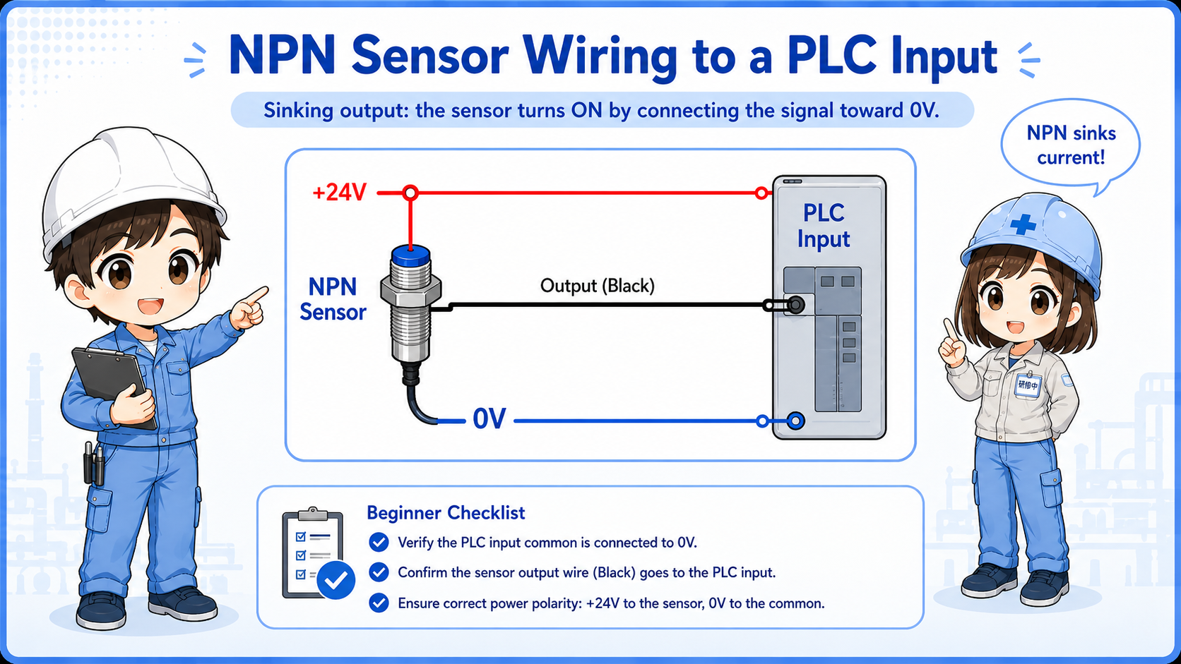
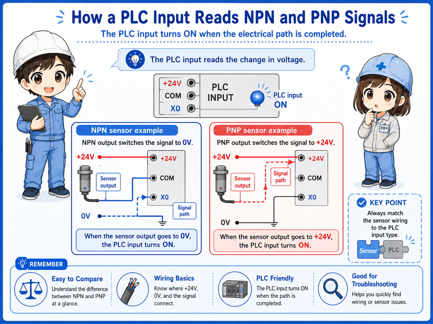
2. NPN output: switching the 0V side
An NPN sensor output is commonly described as a sinking output.
When an NPN sensor turns on, its output transistor connects the signal line toward 0V. The PLC input must be wired so current can flow from the input side through the sensor output to 0V.
Sensor detects
The sensor output turns on.
Output to 0V
The output side provides a path toward 0V.
PLC input ON
The compatible PLC input sees current flow and turns on.
Common wording
NPN is often linked with “sinking output.” Depending on the PLC manual, the input unit side may be described with complementary terms, so always check the actual wiring diagram.
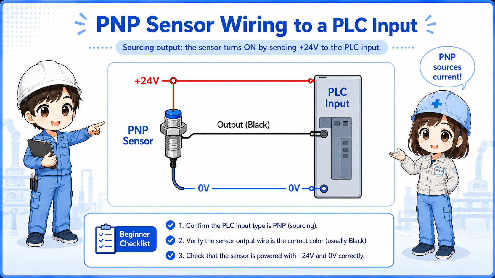
3. PNP output: switching the +24V side
A PNP sensor output is commonly described as a sourcing output.
When a PNP sensor turns on, its output transistor supplies +24V to the signal line. The PLC input must be wired so that receiving +24V at the input terminal turns the input on.
Sensor detects
The sensor output turns on.
Output +24V
The output side supplies +24V to the signal line.
PLC input ON
The compatible PLC input receives the signal and turns on.
4. PLC input unit compatibility
A sensor output must match the PLC input circuit style.
The sensor and PLC input are a pair. If the sensor output type and PLC input unit type do not match, the sensor may turn on physically, but the PLC input monitor may stay off.
| Sensor output | What it does when ON | PLC input must allow | Typical symptom if mismatched |
|---|---|---|---|
| NPN | Switches toward 0V | Current path through input to sensor 0V side | Sensor LED ON but PLC input may not turn on |
| PNP | Supplies +24V | Input turns on when +24V is applied | Voltage appears wrong at the input terminal |
Field-friendly view
If the sensor replacement has the same shape but a different NPN/PNP type, the machine may not read the input correctly even if the sensor itself lights up.
5. Practical wiring checks
When checking NPN/PNP wiring, separate power supply, output signal, and PLC input monitor.
1. Check sensor power
Confirm brown is +24V and blue is 0V, if using the common 3-wire sensor color convention.
2. Check output wire
Confirm what voltage appears on the black output wire when the sensor turns on.
3. Check PLC common wiring
Confirm how the PLC input common is wired and whether it matches NPN or PNP input style.
4. Check input monitor
Look at the PLC input monitor and compare it with the actual sensor state and measured voltage.
Do not judge by wire color only
Brown, blue, and black are common for DC sensors, but terminal function must be confirmed from the actual sensor label or datasheet.
6. Common beginner mistakes
Most NPN/PNP mistakes happen because the sensor output and PLC input are checked separately, not as one circuit.
Mistake 1: sensor LED means PLC input ON
The sensor can detect correctly while the PLC input remains off due to wiring or compatibility mismatch.
Mistake 2: replacing NPN with PNP
The sensor may physically fit, but the output circuit behavior is different.
Mistake 3: ignoring input common
The PLC input common wiring decides which output style can be used correctly.
Mistake 4: mixing manuals and terms
Sinking and sourcing wording can be described from the sensor side or the PLC input side, so the wiring diagram matters more than the label alone.
7. Troubleshooting NPN / PNP sensor inputs
If the PLC input does not turn on, check the signal path in order.
1. Sensor power
Is DC24V supplied correctly to the sensor power wires?
2. Sensor detection
Does the sensor LED or output indicator change when the target is detected?
3. Output voltage
Measure the output wire when the sensor is ON and OFF.
4. PLC input
Does the input monitor change, and does it match the wiring and output type?
8. Practical safety notes
Sensor wiring looks simple, but it can affect machine logic and troubleshooting results.
Always follow the actual wiring diagram, PLC input unit manual, sensor datasheet, and site procedures. Before rewiring or replacing a sensor, confirm the output type, power supply voltage, input unit common wiring, and machine safety conditions.
Keep learning in layers
NPN/PNP becomes easier after you understand DC24V power, PLC inputs, sensor outputs, NO/NC contacts, and how to read input monitor status.