Why a PLC input may not turn on
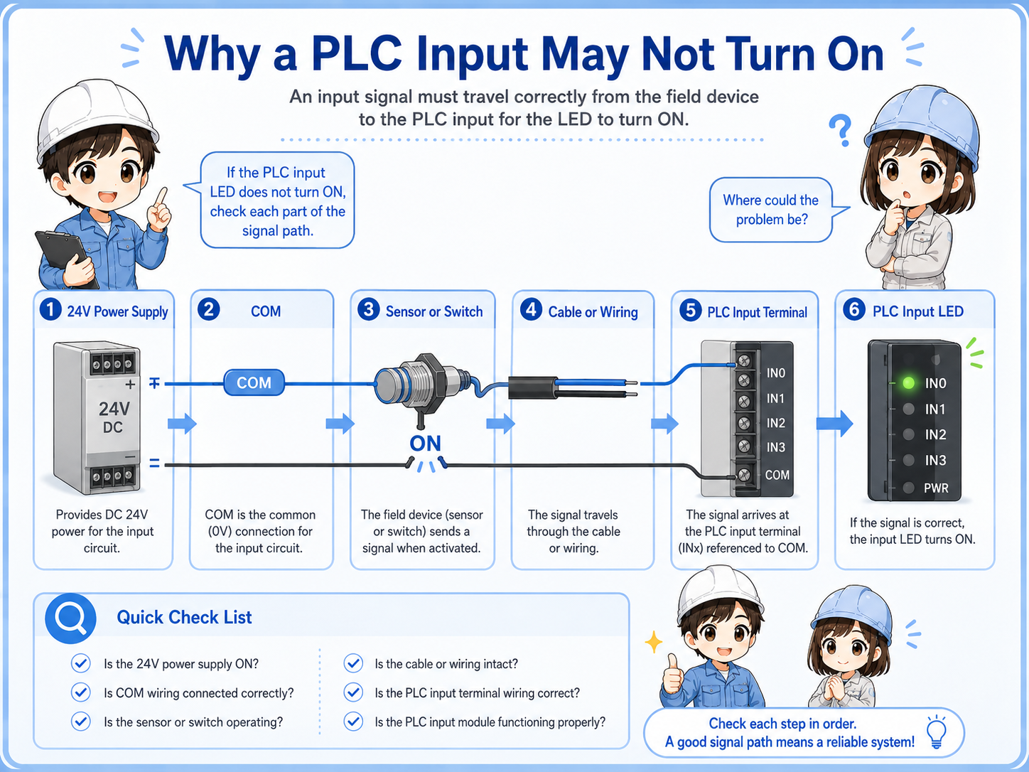
A PLC input does not turn on just because a sensor looks active. The electrical signal must reach the PLC input terminal correctly.
When a PLC input does not turn on, the cause may be on the power supply side, COM wiring, sensor output, cable, connector, input module, or PLC program monitor. If you jump straight to replacement, you may miss a simple wiring or common-terminal issue.
The important field habit is to divide the problem into two parts: whether the field device changes state and whether the PLC receives that electrical signal.

When an input does not turn on, start with the circuit path. Power, COM, sensor output, wire, terminal, and PLC input all matter.

So I should not only look at the sensor lamp. I need to compare it with voltage and the PLC input monitor.
Recommended checking order
Check from the power source toward the PLC input. This keeps the troubleshooting path clear.
1. Confirm 24V power
Check whether the sensor or input circuit has the correct power supply voltage.
2. Confirm COM wiring
Input common wiring determines whether the PLC input can recognize the signal.
3. Check the sensor LED
Move the target and confirm whether the field device changes state.
4. Check the cable and connector
Look for broken wires, loose connectors, oil damage, or intermittent cable movement.
5. Check input terminal voltage
Measure at the PLC input terminal, not only at the sensor side.
6. Check the PLC input monitor
Compare the physical input LED and software monitor before changing the program.
Do not skip COM
Many input problems look confusing when COM wiring is misunderstood. NPN/PNP sensor output and PLC input common must match the circuit design.
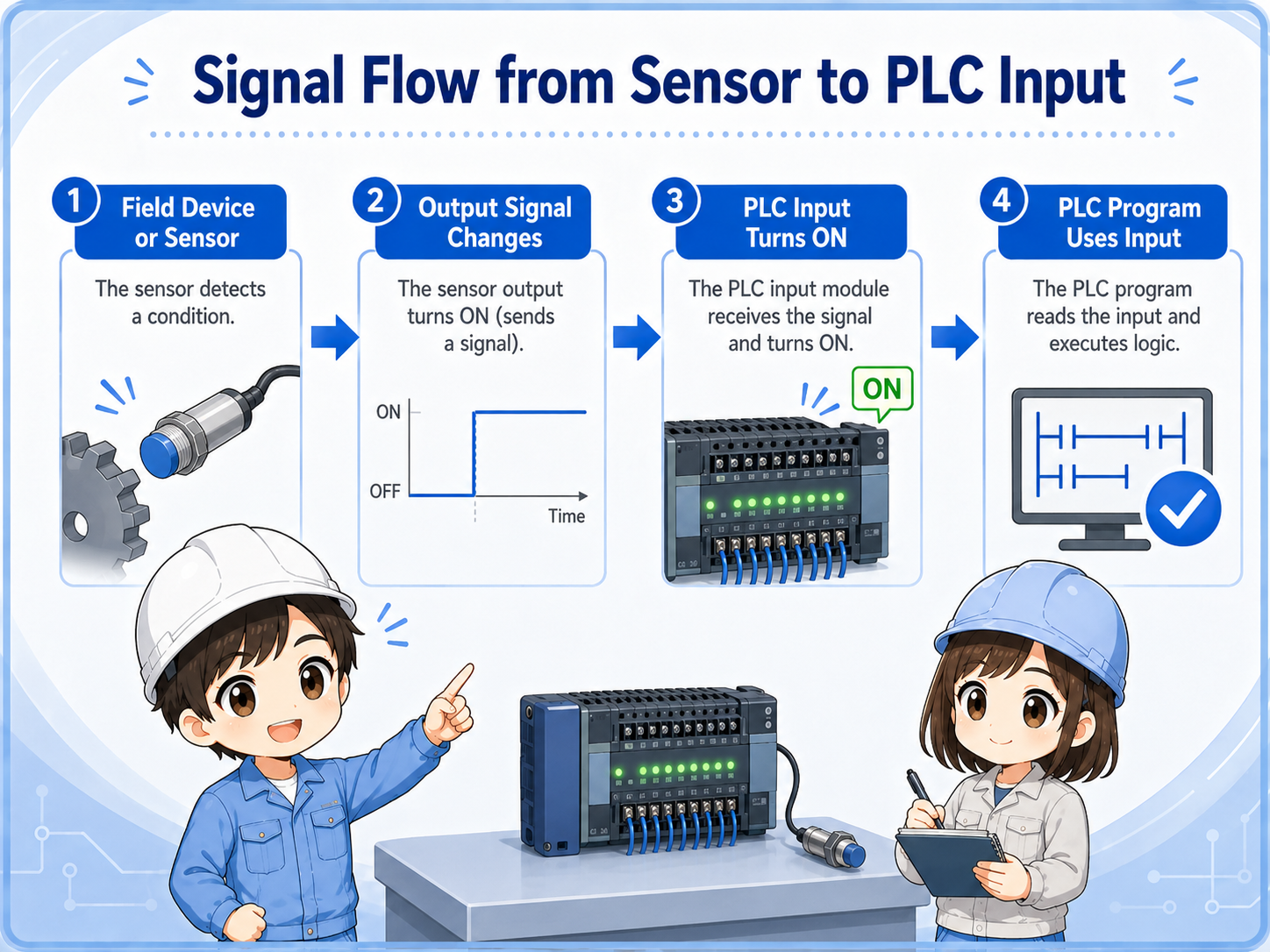
Signal flow from sensor to PLC input
The input signal has to travel from the field device to the input module before the PLC program can use it.
1. Device changes
A sensor, switch, or contact changes state in the machine.
2. Output signal changes
The field device sends or switches the input signal.
3. PLC input turns ON
The input module receives the correct electrical condition.
4. Program uses input
The ladder program uses the input contact in logic.
Sensor ON does not always mean PLC input ON
The sensor can detect correctly, but the PLC may still not receive the signal if wiring, COM, NPN/PNP type, cable, or input module condition is wrong.
Voltage checks at the input circuit
When the visual checks are not enough, measure voltage at the right points and compare the result with the input status.
Do not only measure at the sensor connector. The signal must be confirmed at the PLC input terminal side. This helps separate a field-side detection issue from a wiring or terminal issue.
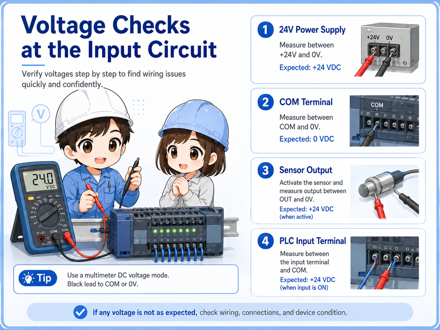
| Check point | What it tells you | Typical next action |
|---|---|---|
| 24V power supply | Whether the input circuit and field device have power. | Check power supply, fuse, terminal block, and distribution wiring. |
| COM terminal | Whether the PLC input common is wired correctly. | Confirm input type and common wiring against the drawing. |
| Sensor output | Whether the field device output changes when the target or switch changes. | Check sensor type, target condition, and sensor wiring. |
| PLC input terminal | Whether the signal actually reaches the input module. | Check cable, connector, terminal screw, and input unit. |
Safety first
Voltage checks must be done according to site rules and by a qualified person. Avoid short circuits, unexpected machine movement, and unsafe live work.
Common trouble patterns
Describe the symptom first. “Never turns ON,” “stays ON,” and “LED changes but PLC input does not” point to different areas.
| Symptom | Likely area | First check |
|---|---|---|
| Sensor LED does not turn ON | Power, target condition, sensor type, sensor failure. | Check 24V power and move the target slowly while watching the LED. |
| Sensor LED turns ON but PLC input does not | Wiring, COM, NPN/PNP mismatch, input terminal, cable break. | Measure voltage at the PLC input terminal and confirm COM wiring. |
| PLC input stays ON | Short circuit, wrong wiring, surrounding metal, stuck contact. | Disconnect or isolate the field side according to site procedure. |
| Input turns ON only sometimes | Loose connector, broken cable, vibration, marginal sensor distance. | Move cable gently, check connector, and confirm mounting stability. |
| Software monitor differs from input LED | Wrong device address, monitor timing, program condition, module issue. | Confirm the input address and compare physical LED with ladder monitor. |
Field checklist before replacing parts
Replacement should come after the circuit path is checked. Otherwise, the same symptom may remain even with a new part.
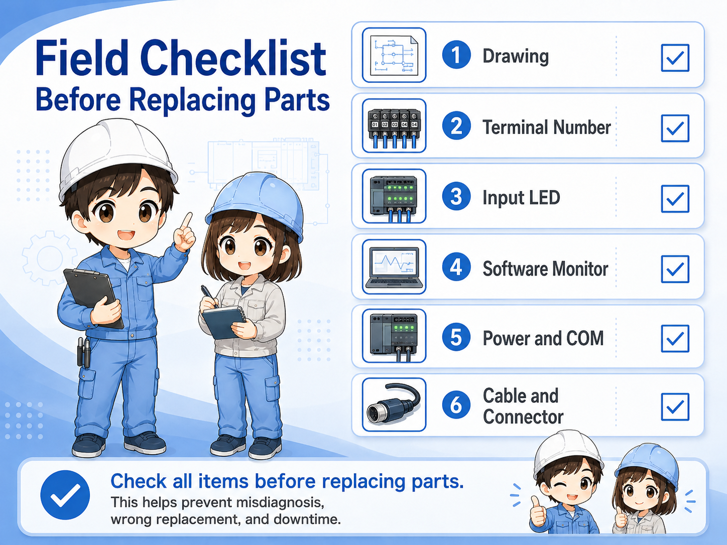
Drawing
Confirm the input number, COM, power supply, and field device wiring from the electrical drawing.
Terminal number
Check that the wire is connected to the expected PLC input terminal.
Input LED
Use the physical PLC input LED as a quick reference, but do not rely on it alone.
Software monitor
Confirm that the monitored device address matches the actual input.
Good field habit
Write down each check result. If several people work on the same issue, a simple check record prevents repeated work and wrong assumptions.
Summary
When a PLC input does not turn on, check the circuit in order instead of replacing parts first. Start with 24V power and COM wiring, then check the field device, cable, PLC input terminal, input LED, and software monitor.
The most important idea is to separate detection from signal reception. A sensor LED may change, but the PLC input may still remain OFF if the electrical signal is not reaching the input module correctly.
Final takeaway
Think in one path: power → COM → field device → cable → PLC input terminal → input LED → PLC monitor. This keeps troubleshooting calm and logical.
Related articles
Read these next to connect input troubleshooting with sensors, NPN/PNP wiring, and PLC basics.