1. The basic idea: a sensor tells the PLC what is happening
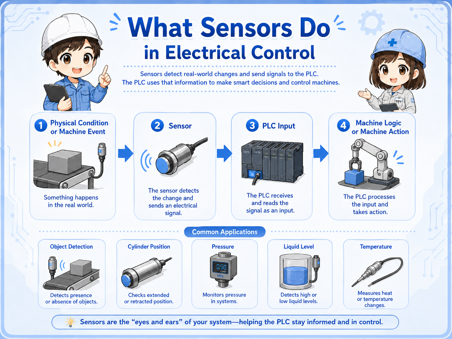
A sensor changes a physical condition into an electrical signal that the control system can use.
In factory equipment, the PLC cannot “see” the machine directly. It needs signals. A sensor detects something in the machine, such as a part arriving, a cylinder reaching the end position, pressure rising, liquid level changing, or temperature going above a set value.
The sensor then sends an electrical signal to the PLC input. The PLC program uses that signal to decide the next action, such as turning on a lamp, moving a cylinder, starting a conveyor, stopping an operation, or showing an alarm.
Short version: physical condition → sensor detection → electrical signal → PLC input → machine logic.
- Detection
- Signal
- PLC input
- Field device
- Wiring check
- Input monitor
The first question to ask
When a machine does not respond, do not ask only “is the sensor broken?” Ask whether the sensor detects, whether its output changes, and whether the PLC input receives the signal.

Senior
A sensor is not just a part with a light on it. It is a signal source for the PLC.

Junior
So if the sensor lamp is on, I still need to check whether the PLC input is on?
Senior
Exactly. Detection, output, wiring, and PLC input status are separate checkpoints.
2. How the PLC sees a sensor
The PLC usually reads the sensor as an input signal, not as the physical object itself.
From the PLC side, a sensor is often just an ON/OFF input. The PLC does not know whether the object is metal, light is blocked, pressure is high, or a float moved unless the wiring and program give that input a meaning.
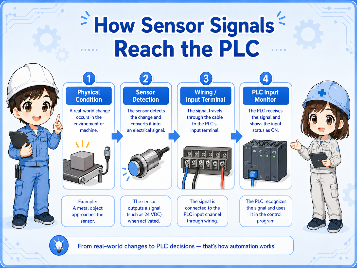
1. Detect
The sensor detects a target, position, level, pressure, flow, or temperature condition.
2. Output
The sensor output changes state, such as ON/OFF or an analog value.
3. Input
The PLC input receives the signal and the program uses it as a condition.
Field-friendly view
If the sensor detects but the PLC input does not change, the problem may be output type, power supply, common wiring, terminal connection, cable damage, or input unit compatibility.
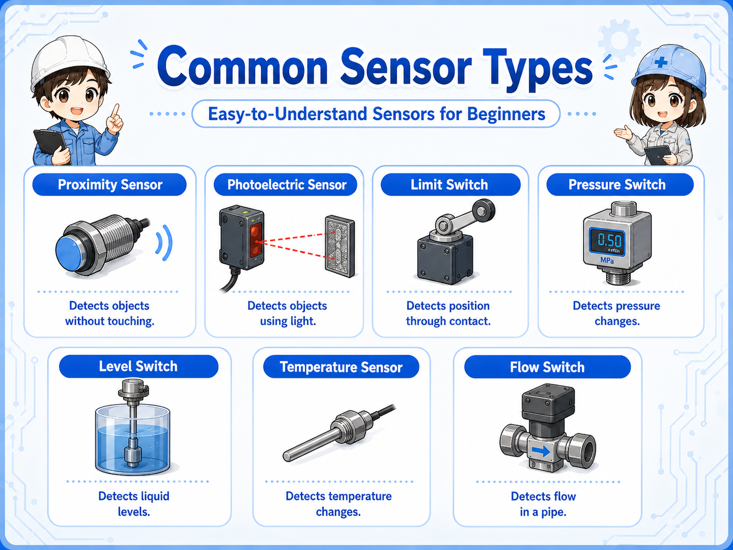
3. Common sensor types in control work
Different sensors detect different physical conditions, but they all become signals for the control system.
Beginners often try to memorize sensor names first. A better approach is to ask what the sensor detects and what signal it sends. Once you know the detection target, the wiring and PLC input check become easier to understand.
| Sensor type | What it detects | Typical use | Common check point |
|---|---|---|---|
| Proximity sensor | Object near the sensing face, often metal depending on sensor type. | Part detection, cylinder position, jig position. | Distance, mounting position, target material, output type. |
| Photoelectric sensor | Light received, reflected, or blocked. | Workpiece passing, object presence, conveyor detection. | Lens dirt, alignment, reflection, sensitivity setting. |
| Limit switch | Mechanical contact by lever, roller, or actuator. | End position, door position, mechanical confirmation. | Actuator movement, contact wear, mounting looseness. |
| Pressure switch | Pressure reaching a set point. | Air pressure confirmation, vacuum confirmation. | Set value, actual pressure, tubing, response delay. |
| Float / level switch | Liquid level or float movement. | Tank level, overflow prevention, low-level detection. | Float movement, sticking, orientation, cable condition. |
| Temperature sensor | Temperature value or temperature threshold. | Heater control, cooling check, abnormal temperature detection. | Sensor type, scaling, broken wire, controller setting. |
| Flow switch | Flow present, stopped, or above a set point. | Cooling water, air flow, pump confirmation. | Actual flow, clogging, direction, set point. |
4. Sensor signal types: ON/OFF, analog, NPN, PNP, NO, and NC
A sensor name alone is not enough. You also need to know what kind of signal it sends.
Many basic sensors send a digital ON/OFF signal. Other sensors send analog values such as 0-10V or 4-20mA. In practical PLC input work, you also need to check whether the output is NPN or PNP, and whether the contact behavior is NO or NC.
| Signal / output idea | What it means | Why it matters |
|---|---|---|
| Digital ON/OFF | The signal is mainly ON or OFF. | Used for many PLC input checks and ladder conditions. |
| Analog signal | The signal changes as a value, such as voltage or current. | Used for pressure, temperature, level, flow, and position values. |
| NPN / PNP | How the sensor output switches the PLC input circuit. | A mismatch can make the PLC input stay off even when the sensor detects. |
| NO / NC | Whether the contact is open or closed in the normal state. | Important for stop signals, interlocks, alarms, and input logic. |
| 2-wire / 3-wire | How the sensor power and output are wired. | Wiring method affects voltage checks and replacement work. |
Do not replace only by shape
Two sensors may look similar but have different output type, sensing distance, power supply, wiring method, or signal behavior. Always check the model and specifications.
5. Mounting and adjustment points
Many sensor problems are caused by position, distance, dirt, vibration, or mechanical changes rather than a broken sensor.
Before assuming the sensor has failed, check whether the target reaches the detection area correctly. In actual equipment, brackets can loosen, workpieces can shift, air cylinders can stop slightly short, reflective surfaces can change, and dust or oil can cover the sensing face.
Detection distance
Is the target close enough, and is the sensor type suitable for the target material or surface?
Mounting position
Has the bracket moved, bent, loosened, or been replaced at a slightly different angle?
Environment
Is there dust, oil, water, metal chips, vibration, light interference, or cable stress?
Adjustment setting
Does the sensitivity, threshold, teach setting, or pressure set point match the actual process?
Practical view
If a sensor problem appears after maintenance, setup change, product change, or mechanical work, check alignment and mechanical position before replacing electrical parts.
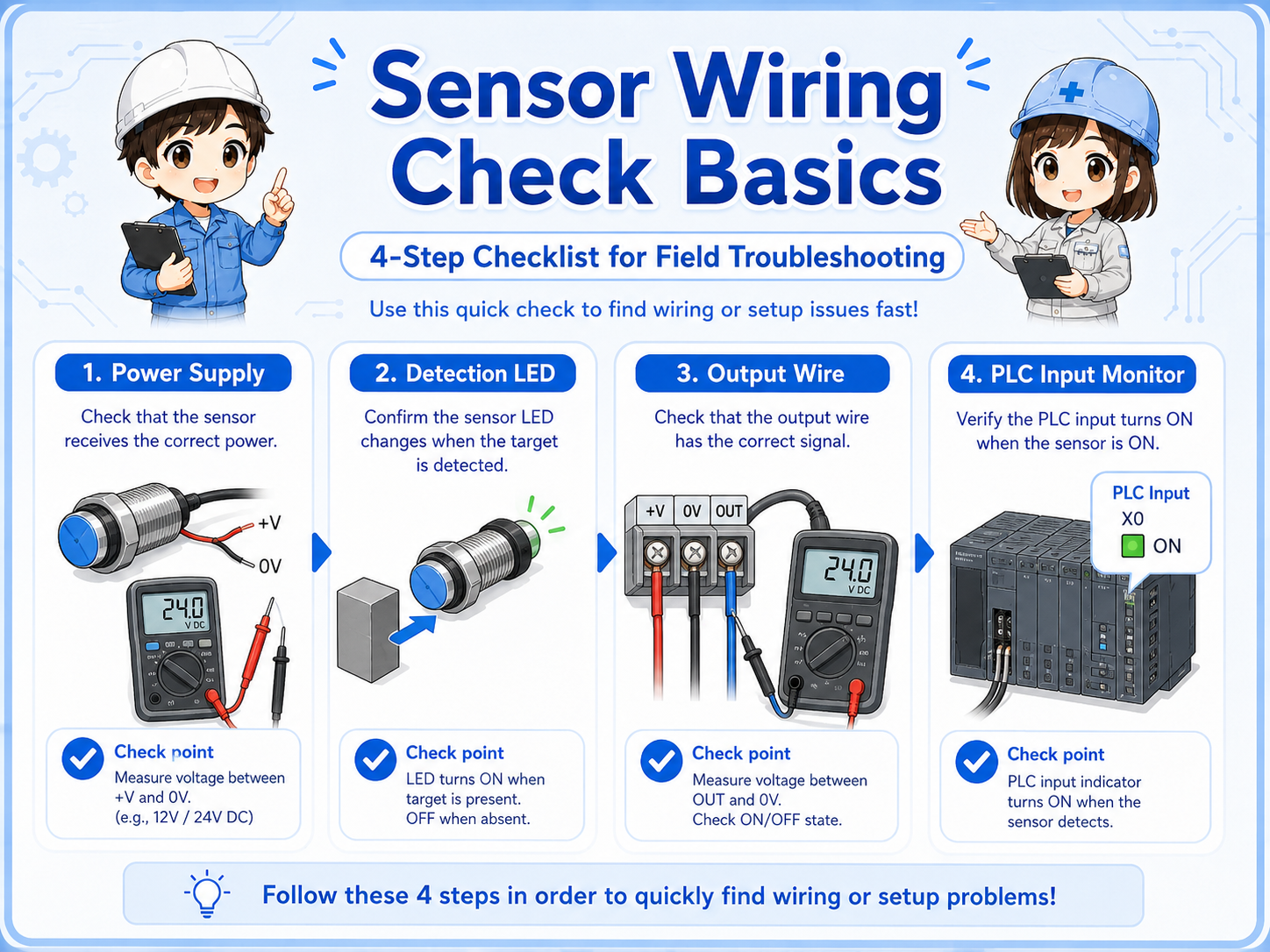
6. Practical wiring checks
Sensor troubleshooting becomes easier when you separate power supply, output signal, and PLC input monitor.
A common mistake is checking only the sensor indicator light. The indicator is useful, but it does not prove that the PLC input is receiving the correct signal. The signal must pass through wiring, terminals, common wiring, and the input unit.
1. Check sensor power
Confirm that the sensor has the correct power supply, such as DC24V, and that polarity is correct.
2. Check detection state
Confirm whether the sensor indicator changes when the target is present or absent.
3. Check output signal
Measure the output wire or contact state while the sensor is ON and OFF.
4. Check PLC input
Compare the measured signal with the PLC input monitor and the program condition.
Be careful with live measurements
Follow site rules and safe measurement procedures. If the circuit involves moving machinery, safety devices, or hazardous energy, do not bypass sensors casually.
7. Common beginner mistakes
Sensor checks become unreliable when the physical detection and electrical signal are mixed together.
Mistake 1: sensor lamp ON means PLC input ON
The sensor may detect correctly, but wiring, output type, input common, or terminal connection can still prevent the PLC input from turning on.
Mistake 2: replacing by appearance only
The same shape may have different output type, cable length, sensing distance, response, connector pinout, or NO/NC behavior.
Mistake 3: ignoring mechanical position
The sensor may be normal, but the target may not reach the detection range due to bracket movement, cylinder stroke, or workpiece variation.
Mistake 4: checking only the field side
Always compare the physical sensor status with the PLC input monitor and the program logic.
Small difference, big effect
A sensor problem can look like a PLC problem, a wiring problem, a mechanical problem, or a process problem. That is why separating the checks is important.
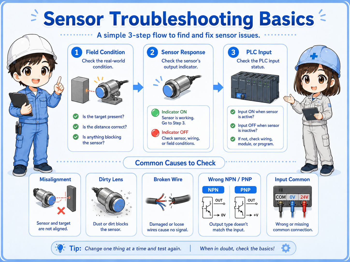
8. Troubleshooting sensor problems
When a sensor-related problem happens, move from the field condition toward the PLC input step by step.
Field condition
Is the target, pressure, level, flow, position, or temperature condition actually present?
Sensor response
Does the indicator or output status change when the condition changes?
PLC input
Does the PLC input monitor change in the same way the drawing expects?
Junior
The sensor light turns on, but the machine still waits. Should I replace the sensor?
Senior
Not yet. Check the output wire, terminal, common wiring, PLC input monitor, and the program condition first.
9. Practical safety notes
Sensors can be part of machine operation, interlocks, alarms, and safety-related systems.
Some sensors only provide process information. Others may be used in stop conditions, interlocks, position confirmation, vacuum confirmation, pressure confirmation, or safety-related functions. Always check the drawing and site procedure before changing wiring, bypassing a signal, or replacing a sensor.
Do not bypass casually
Temporarily forcing or bypassing a sensor can move equipment unexpectedly. Follow lockout/tagout rules, machine-specific procedures, and instructions from responsible personnel.
Keep learning in layers
Sensor checks become easier when you understand PLC inputs, NO/NC contacts, NPN/PNP output types, DC24V wiring, and how to use the PLC input monitor.