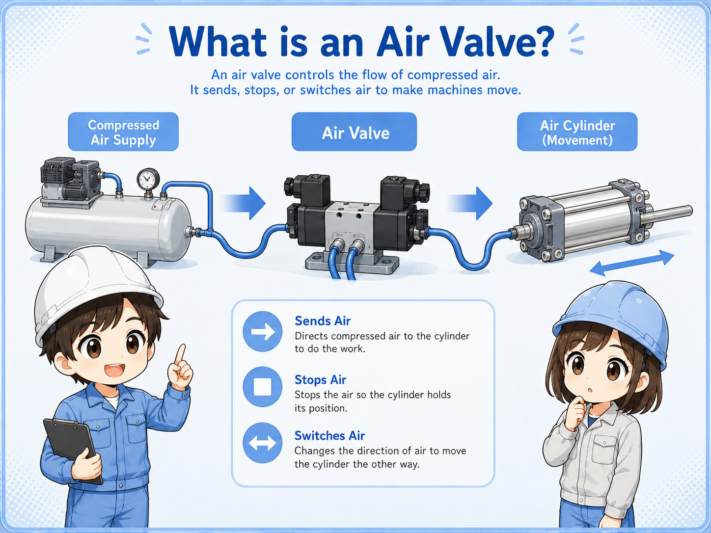
What is an air valve?
An air valve controls compressed air by sending it, stopping it, or switching its direction.
In factory automation, compressed air is often used to move cylinders, grippers, stoppers, and small mechanisms. The air valve, sometimes called a pneumatic valve or directional control valve, is the part that decides where the air goes. Actual port labels, valve symbols, normal state, and piping method depend on the valve model and pneumatic circuit drawing.
From an electrical control point of view, the important idea is simple: the PLC output can energize a solenoid coil, the valve changes state, and the air cylinder moves.

When an air cylinder does not move, check both sides. The electrical signal may be correct, but the air side may still have a problem.

So I should check the PLC output, solenoid coil, air pressure, valve manual override, tubes, and cylinder movement in order.
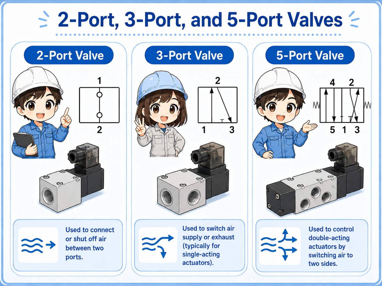
2-port, 3-port, and 5-port air valves
The number of ports tells you how the valve connects air supply, output, and exhaust paths.
Air valves are often described by the number of ports. A port is an air connection point. For beginners, it is enough to understand the role before memorizing every symbol.
| Valve type | Basic role | Typical use |
|---|---|---|
| 2-port valve | Opens or closes one air path. | Simple air supply ON/OFF. |
| 3-port valve | Switches between supply and exhaust for one output line. | Single-acting cylinder or air blow control. |
| 5-port valve | Switches air between two cylinder ports and exhausts the other side. | Double-acting air cylinder control. |
Check the actual symbol
Port count is a useful starting point, but valve operation also depends on positions, normal state, pilot type, and manufacturer symbol. Always check the drawing and manual.
How an air valve moves an air cylinder
A double-acting cylinder moves because air is supplied to one side while the other side is exhausted.
For a typical double-acting cylinder, a 5-port valve switches air to either side of the cylinder. When air enters one side, the piston moves. The air on the opposite side must have an exhaust path.
1. PLC output turns ON
The PLC output energizes the solenoid coil.
2. Valve switches
The valve changes the air path.
3. Cylinder moves
Compressed air pushes the piston and the mechanism moves.
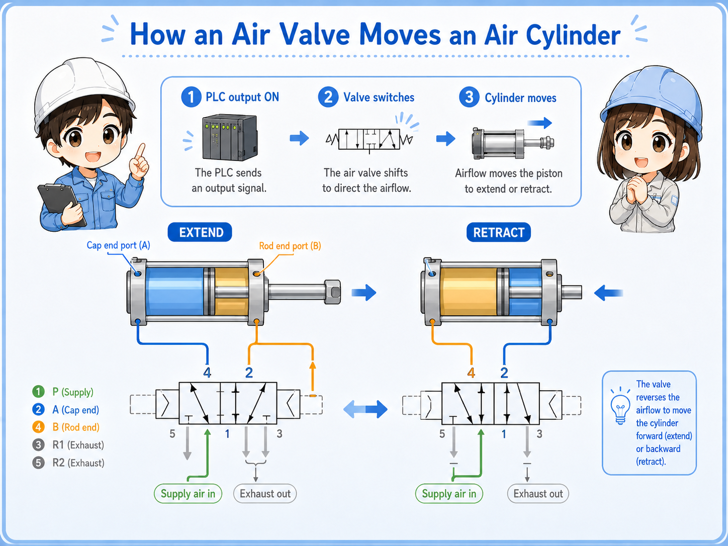
Do not forget exhaust
If the exhaust path is blocked or the speed controller is closed too much, the cylinder may move slowly or not move even when air is supplied.
Solenoid valve and PLC output
A solenoid valve connects electrical control and pneumatic movement.
A solenoid valve has a coil. When the coil is energized, the valve changes state. In many machines, a PLC output turns the coil ON and OFF.
If the cylinder does not move, separate the problem into electrical and pneumatic checks. For example, the PLC output may be ON, but the coil may not receive voltage. Or the coil may energize, but the air supply may be missing.
| Check point | What it tells you | First action |
|---|---|---|
| PLC output LED | Whether the PLC is commanding the output. | Compare with the ladder monitor and output terminal. |
| Coil voltage | Whether the valve coil receives the correct voltage. | Measure at the valve connector or terminal. |
| Manual override | Whether the valve and air side can move independently of the PLC output. | Operate only if it is safe and allowed by site rules. |
| Air pressure | Whether enough compressed air is supplied. | Check regulator, shutoff valve, and pressure gauge. |
Manual operation can move the machine
Using a manual override may move a cylinder unexpectedly. Always follow site safety rules and confirm the machine condition before operating it.
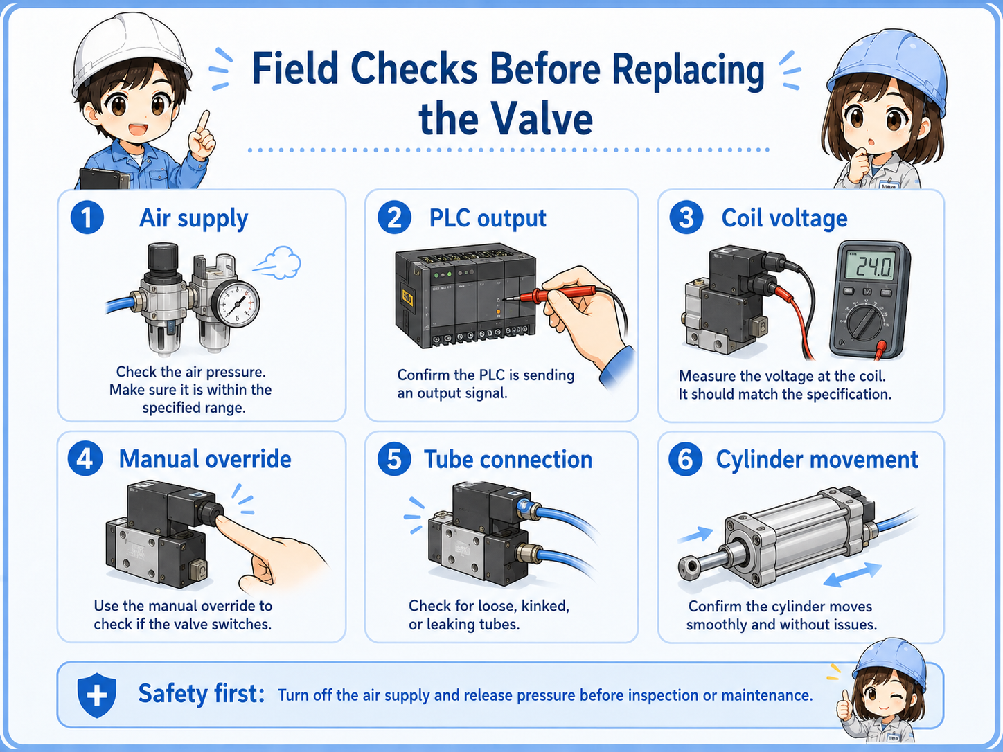
Field checks before replacing the valve
An air valve problem is not always the valve itself. Check the signal and the air path before replacement.
1. Air supply
Check main air pressure, regulator setting, and shutoff valve position.
2. PLC output
Confirm whether the PLC output is turning ON when the machine should move.
3. Coil voltage
Measure whether the solenoid coil receives the correct voltage.
4. Manual override
If safe, use the manual override to separate valve/air issues from electrical issues.
5. Tube connection
Check for disconnected tubes, reversed ports, bent tubes, or air leaks.
6. Cylinder movement
Check whether the cylinder is mechanically stuck, overloaded, or blocked.
Common trouble patterns
The symptom helps you decide whether to start from the electrical side, air supply side, valve body, or cylinder side.
| Symptom | Likely area | First check |
|---|---|---|
| Cylinder does not move | No air, no coil voltage, wrong valve state, stuck cylinder. | Check air pressure, PLC output, coil voltage, and manual override. |
| Valve clicks but cylinder does not move | Air pressure, tube connection, port issue, cylinder mechanical load. | A click sound does not always prove that the valve is passing air correctly. Check supply pressure, exhaust path, port connection, valve operation, and cylinder mechanical load. Use manual override only when the machine condition is safe and the site procedure allows it. |
| Cylinder moves slowly | Low pressure, speed controller, air leak, exhaust restriction. | Check regulator, speed controller, tubes, and muffler. |
| Air keeps leaking | Seal wear, tube damage, fitting leak, valve internal leak. | Listen for leakage and isolate the area safely. |
| Movement direction is reversed | Tubes connected to the wrong ports. | Check the port labels and drawing before swapping tubes. |
Good field habit
Before changing tube connections, take a photo of the current state. Reversed tubes can create confusing movement and make troubleshooting harder.
Summary
An air valve controls compressed air by sending, stopping, or switching the flow. In factory automation, it often works with a PLC output, solenoid coil, and air cylinder.
When a cylinder does not move, do not assume the valve is bad immediately. Check the air supply, PLC output, coil voltage, valve manual override, tube connection, exhaust path, and cylinder condition in order.
Final takeaway
Think in two layers: the electrical command switches the valve, and the pneumatic circuit moves the cylinder. Both layers must be checked.
Related articles
Read these next to connect pneumatic valves with PLC outputs, cylinders, and sensor checks.