What is a delayed start circuit?
It is a circuit that waits for a set time before turning an output ON.
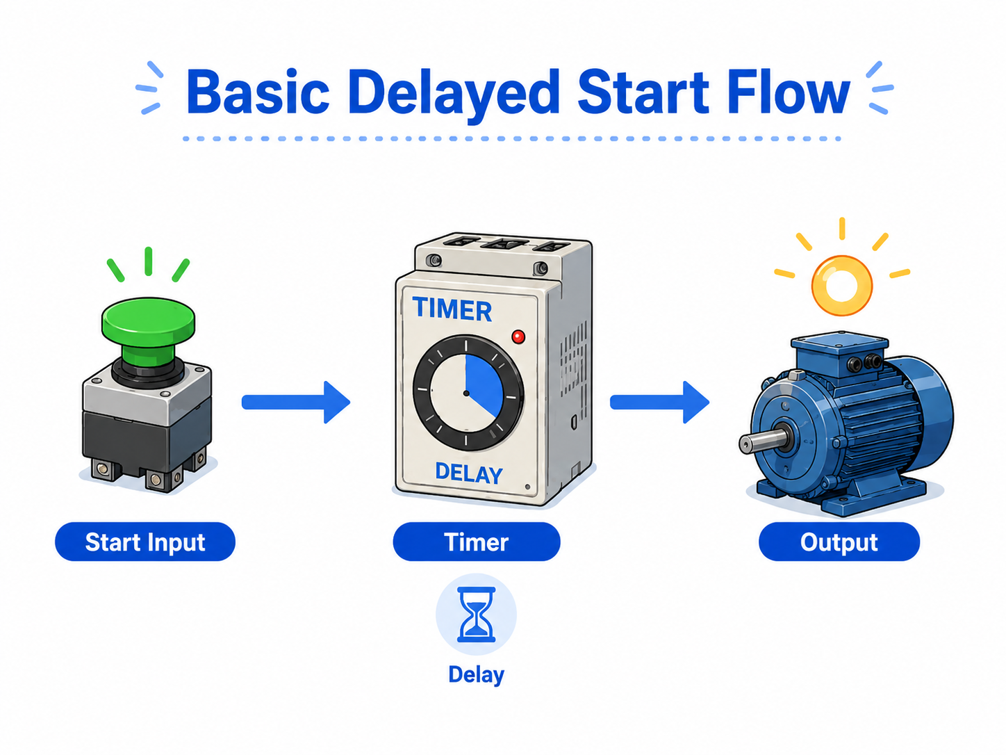
A delayed start circuit is used when an output should not start immediately after the input turns ON. Instead, the circuit starts a timer first. When the timer reaches the preset time, the output is allowed to turn ON.
This is often written as a simple sequence: input ON → timer starts → preset time elapses → output ON. Once you understand this flow, many timer-based circuits become easier to read.
Simple way to remember
Do not think of the output first. Think of the timer first: the input starts the timer, and the completed timer contact starts the output.
Why delayed start circuits are used
The delay helps equipment start in the right order and prevents sudden operation.
In control panels, some devices should start only after another condition is ready. For example, a fan may start after a damper opens, a conveyor may start after a warning lamp or buzzer, or a second motor may start after the first motor has stabilized.
The delay does not make the circuit complicated by itself. It simply adds a waiting step between the start condition and the output.
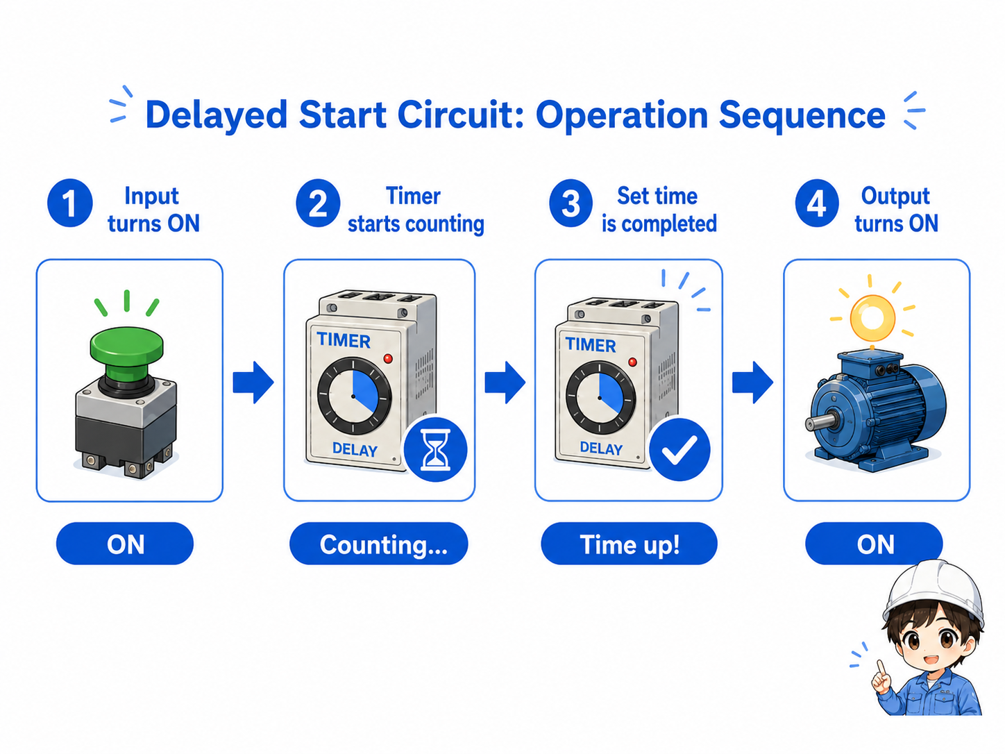
1. Start condition
A push button, sensor, relay contact, or PLC bit turns ON.
2. Timer counts
The timer begins counting while the condition remains true.
3. Time is complete
The timer done contact or timer output becomes true.
4. Output starts
The motor, lamp, solenoid, or next step turns ON.
Basic ladder logic idea
In ladder logic, the timer instruction is placed before the output condition.
In a simple PLC example, the start input energizes an ON-delay timer. After the preset time, the timer done bit becomes true. That done bit is then used to turn the output ON.
For beginners, it is helpful to read the circuit in two separate parts: first, what starts the timer; second, what uses the timer completion signal.


SeniorWhen you read a delayed start circuit, do not jump straight to the output. First, find what condition starts the timer.

JuniorSo if the output does not turn ON, I should check whether the timer is actually counting and whether it has completed.
Timer behavior depends on the instruction
The exact timer name, preset format, reset behavior, and done bit name depend on the PLC manufacturer and instruction type. Always confirm the actual program and manual.
Typical applications in the field
Delayed start is common when equipment should not operate at the same moment.
The same idea appears in many machines. The output may be a motor, fan, conveyor, lamp, buzzer, valve, or the next step of a sequence. The timer gives the system a short preparation time.
| Example | Why delay is used | What to check |
|---|---|---|
| Warning before start | A buzzer or lamp operates before a conveyor starts. | Check whether the warning signal and timer are active. |
| Sequential motor start | Motors are started one by one instead of all at once. | Check the start order and each timer preset. |
| Air or hydraulic preparation | The machine waits for pressure, position, or readiness. | Check sensors, pressure switches, and interlock contacts. |
Field point
A delayed start circuit is often part of a larger sequence. If the output does not start, the cause may be before the timer, inside the timer condition, or after the timer done contact.
Field checks when the delayed output does not start
Separate the problem into input condition, timer operation, and output side.
When troubleshooting, do not replace the output device immediately. First check whether the timer is being enabled. Then check whether the preset time has elapsed and whether the timer done condition is turning ON. Finally, check the output circuit.
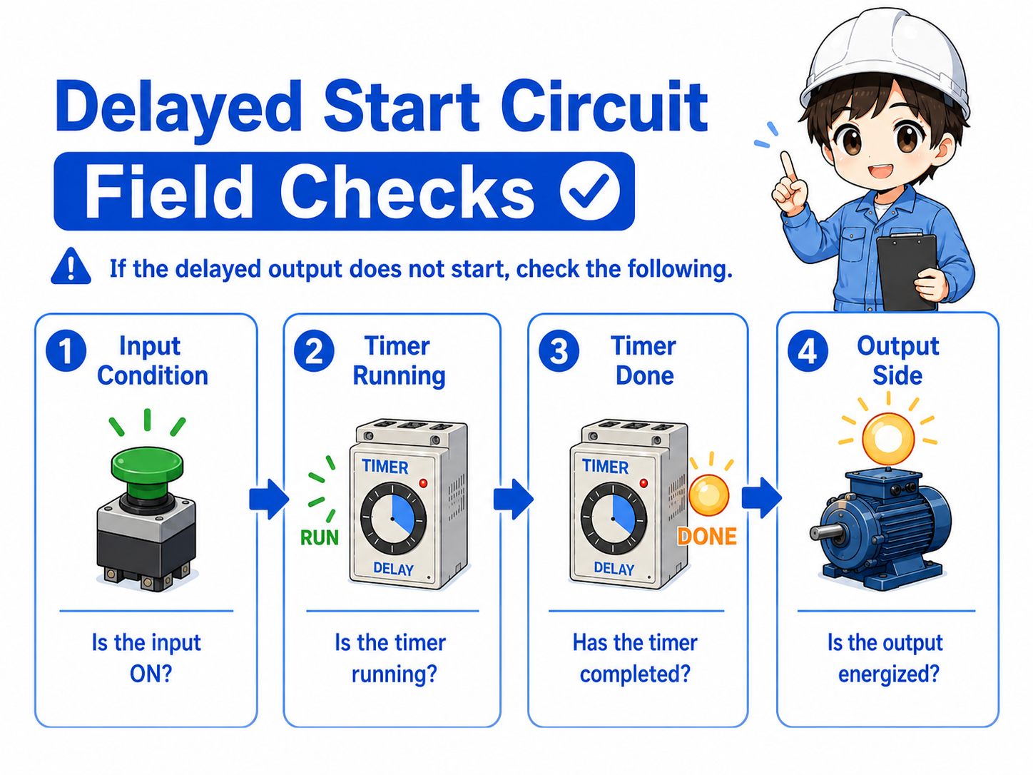
Check the input condition
Is the start input, sensor, or interlock contact actually ON?
Check timer counting
Is the timer enabled and counting while the condition remains true?
Check timer completion
Has the preset time elapsed, and is the done bit or contact ON?
Check the output side
After the timer completes, is the PLC output, relay, or load side working?
Do not bypass safety circuits
If the delayed start is connected to a safety-related function, do not bypass interlocks for convenience. Confirm the machine design and safety requirements before making changes.