What is a pilot lamp?
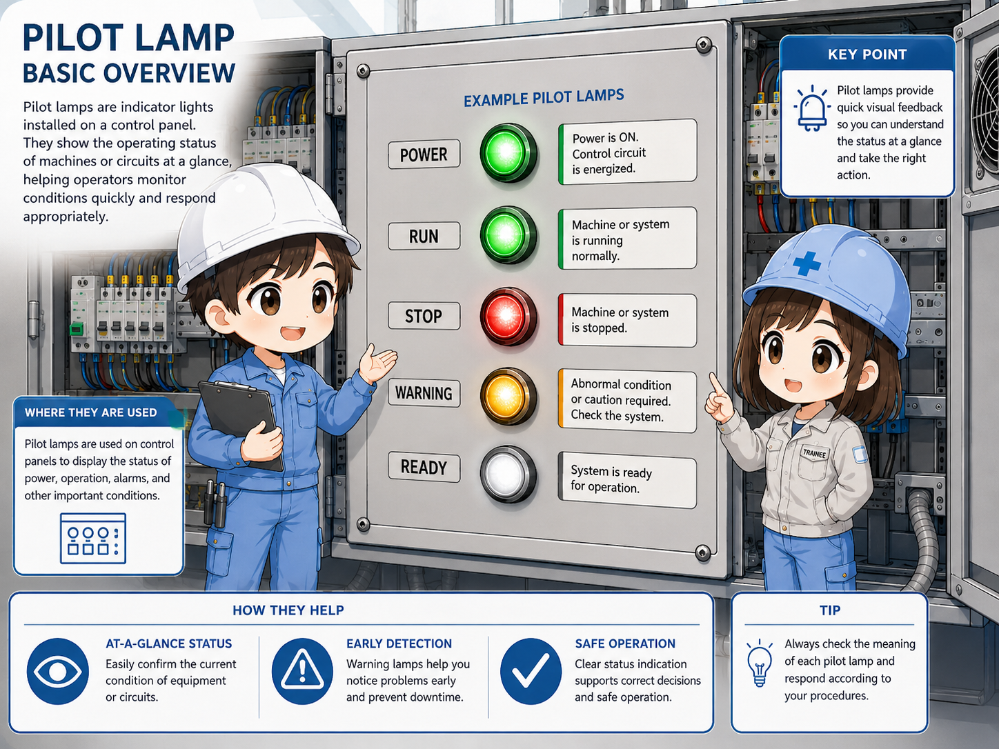
A pilot lamp is a small indicator light used to show the current status of a machine, circuit, or panel.
In a control panel or operator panel, a pilot lamp gives a quick visual message. It may show that power is on, a machine is running, a stop condition is active, an alarm has occurred, or a certain operation is ready.
The important point is that a pilot lamp is mainly a display device. It does not control the machine by itself. It shows a status that comes from a switch, relay contact, PLC output, or another control signal.
Read the lamp as a message
A lamp is useful only when the color, label, and circuit meaning are clear. Always read the lamp nameplate or drawing together with the color.
What pilot lamps show
A pilot lamp usually tells you the result of a control condition, not the whole reason behind it.
For example, a green lamp may show that a motor is running, but it may not tell you whether the command came from a manual switch, an automatic sequence, or a PLC program. The lamp only shows the status assigned to that lamp circuit.
- Power available: the control circuit or main power is energized.
- Run condition: a motor, pump, fan, or machine sequence is operating.
- Stop or ready condition: the machine is stopped, ready, or waiting.
- Warning or alarm: a fault, abnormal condition, or attention state is active.

A lamp tells us what the panel wants to show. To know why it is on or off, we still need to check the drawing, PLC output, relay contact, and actual voltage.

So I should not assume the cause from the lamp alone. I should use it as the starting point for checking the circuit.
Common pilot lamp colors
Lamp colors are helpful, but the final meaning depends on the machine design, label, and drawing.
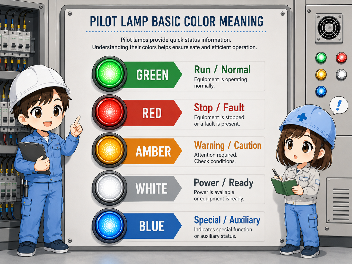
Many panels use familiar color meanings such as green for run, red for stop or fault, and amber for warning. However, color use can vary by machine, company standard, and application. Do not rely on color alone.
| Color | Common use | Field note |
|---|---|---|
| Green | Run, normal operation, ready | Check whether it means command on, output on, or actual running feedback. |
| Red | Stop, fault, trip, emergency-related status | Read the label carefully because red may mean different stop or fault states. |
| Amber | Warning, attention, abnormal but not stopped | Often used before a full fault or for a caution condition. |
| White / Blue | Power, mode, auxiliary status, special indication | Meaning depends strongly on the panel standard and nameplate. |
Color is not a universal guarantee
Always follow the actual machine documentation, customer standard, and applicable safety rules. This guide explains common practical patterns, not a legal color standard.
How a pilot lamp is usually wired
A lamp turns on when voltage is applied to the lamp circuit through a contact, relay, PLC output, or other signal source.
A pilot lamp may be connected to AC or DC depending on the panel design and lamp rating. Many control panels use 24V DC lamps driven by PLC outputs or relay contacts, but other voltages are also possible.
1. Status condition
A switch, relay, PLC, or sensor condition becomes active.
2. Output path
The control circuit sends voltage through a contact or output.
3. Lamp circuit
The lamp receives its rated voltage and turns on.
4. Visual check
The operator sees the panel status from the lamp.
Separate command and lamp problems
If a lamp is off, the problem may be the command signal, wiring, power supply, lamp unit, terminal connection, or the lamp itself. Check them step by step.
Field checks when a lamp does not turn on
Check whether the lamp should be on first, then check the signal, voltage, terminals, and lamp unit.
A common mistake is replacing the lamp immediately. Before that, confirm whether the control condition is actually active. If the PLC output or relay contact is not turning on, a new lamp will not solve the problem.

Should the lamp be on?
Confirm the operation condition, alarm condition, or PLC output command first.
Is voltage present?
Measure the actual lamp voltage only when it is safe and permitted by site rules.
Are terminals tight?
Loose terminals, broken wires, or poor contacts can stop the lamp from turning on.
Is the lamp unit correct?
Check the rated voltage, lamp type, LED polarity if applicable, and replacement part.
Safety first
Do not touch live parts casually. Follow lockout, measurement, and electrical safety procedures at the site.
Common mistakes
Most mistakes come from reading a lamp as a full explanation instead of a simple status signal.
- Assuming the machine is safe only because a green lamp is on.
- Assuming the lamp is broken without checking the command signal.
- Replacing a lamp with a different voltage rating.
- Ignoring LED polarity or AC/DC rating.
- Reading color without checking the label, drawing, or machine standard.
Summary: a pilot lamp is a visual status clue
A pilot lamp helps people understand control panel status quickly. It may show power, run, stop, ready, warning, or fault conditions, depending on the machine design.
When checking a lamp, do not look at the light alone. Check the label, color, drawing, command signal, voltage, terminals, and lamp unit together. This gives a much more reliable understanding of what the panel is showing.