What is a Manual/Auto selector circuit?
It is a circuit that selects which command path can control one output.
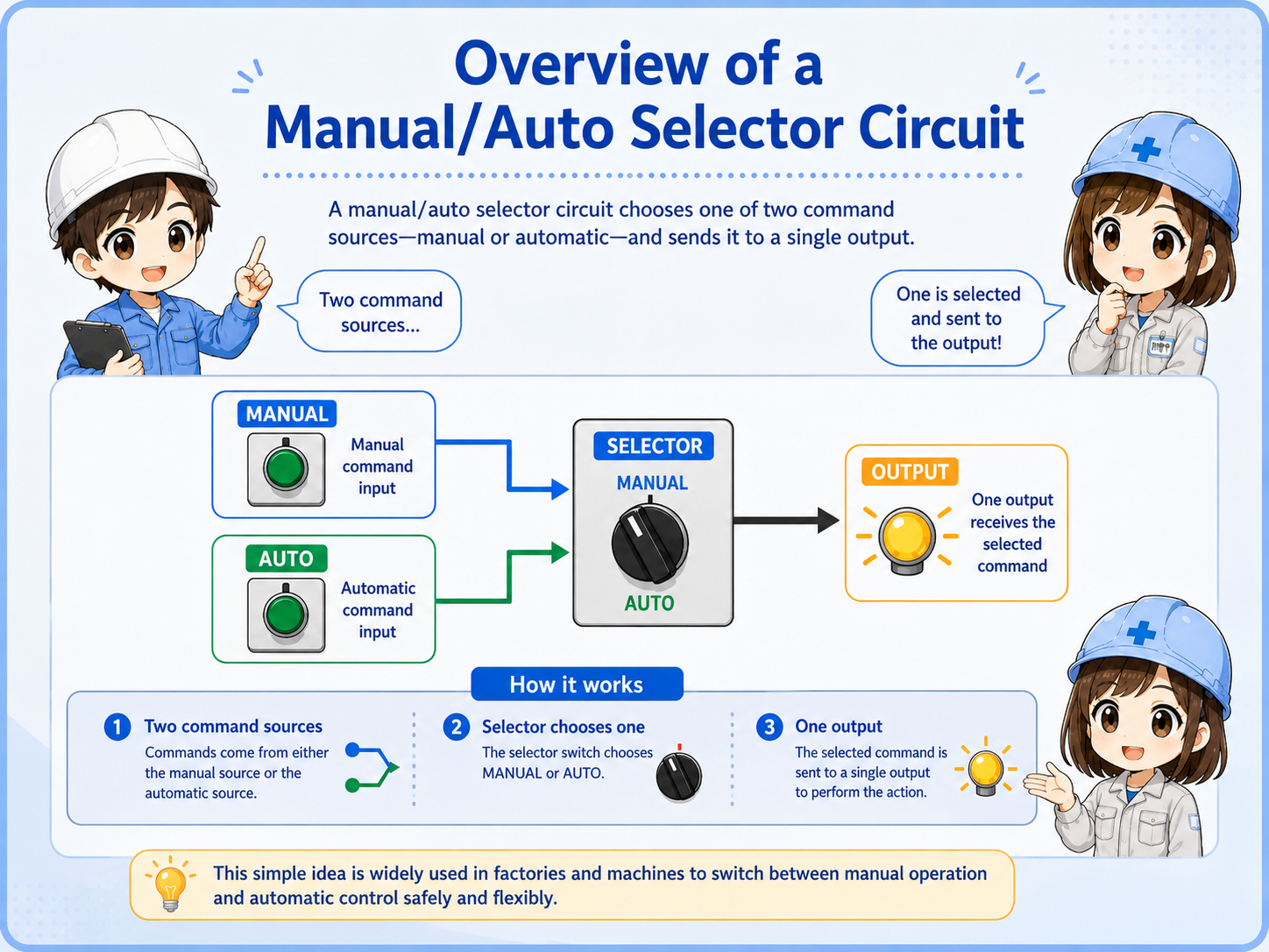
In many control panels, one output can be commanded in two ways. A manual command may come from a push button or local operation switch. An automatic command may come from a PLC output, sequence condition, or relay logic.
The selector circuit decides which command path is active. This prevents manual and automatic commands from being mixed without a clear rule.
Think in command paths.
The useful question is not only “Where is the selector knob?” It is “Which signal is allowed to reach the output right now?”
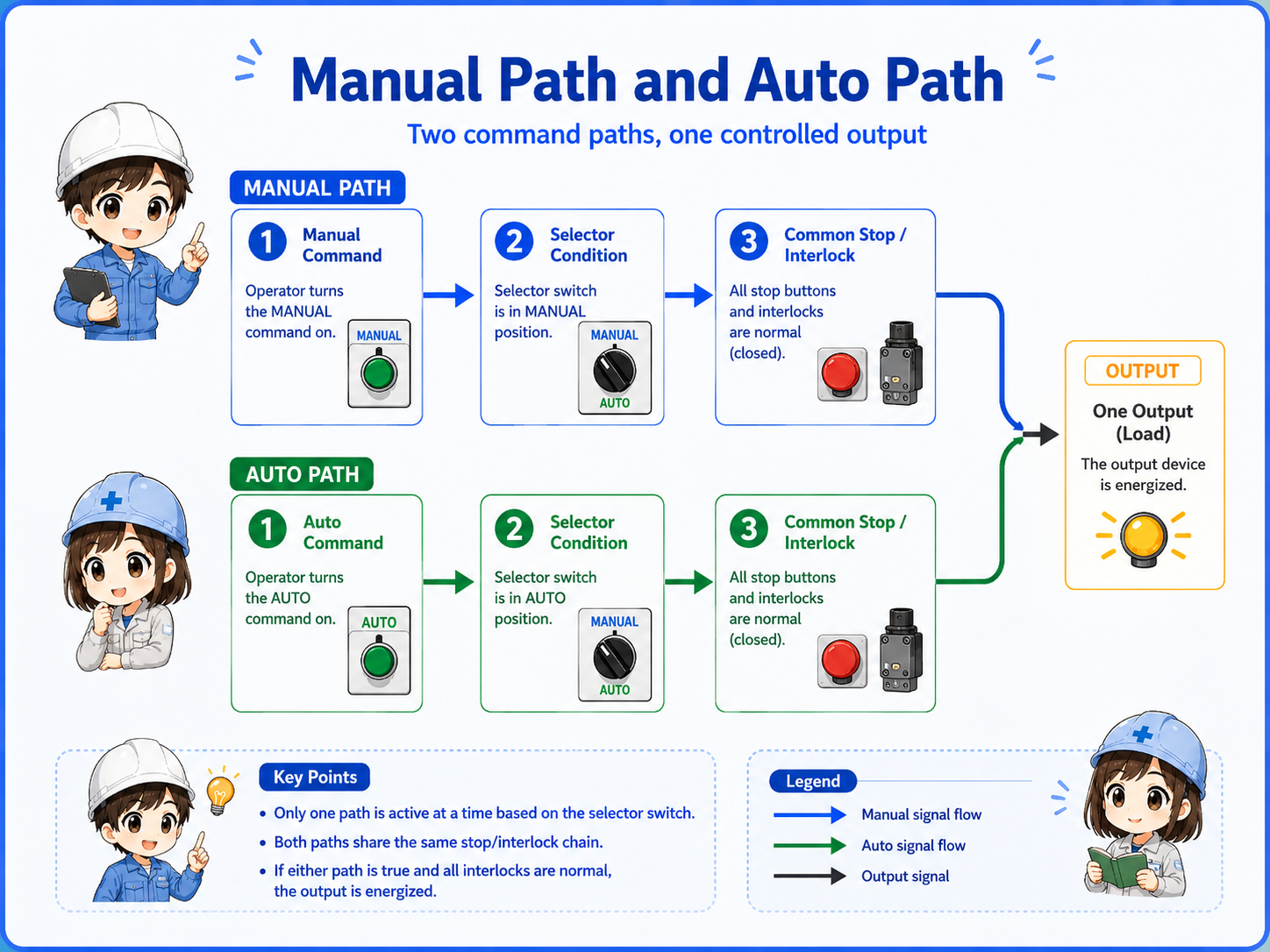
Manual path and Auto path
The manual path is normally used for setup, adjustment, jogging, or local operation. The auto path is normally used for normal sequence operation.
Both paths may eventually operate the same relay, solenoid valve, lamp, or PLC output, but they should pass through clear selection and common stop conditions.
1. Manual command
Local push button or operation switch.
2. Auto command
PLC or automatic sequence condition.
3. Selector state
Only the selected path continues.
4. Output
The selected path drives the output.
The selector switch is the traffic gate
A Manual/Auto selector switch usually has contacts that change state depending on the selected position. In Manual position, the manual path is allowed. In Auto position, the automatic path is allowed.
A 3-position selector may also have a center Stop or OFF position that blocks both command paths.
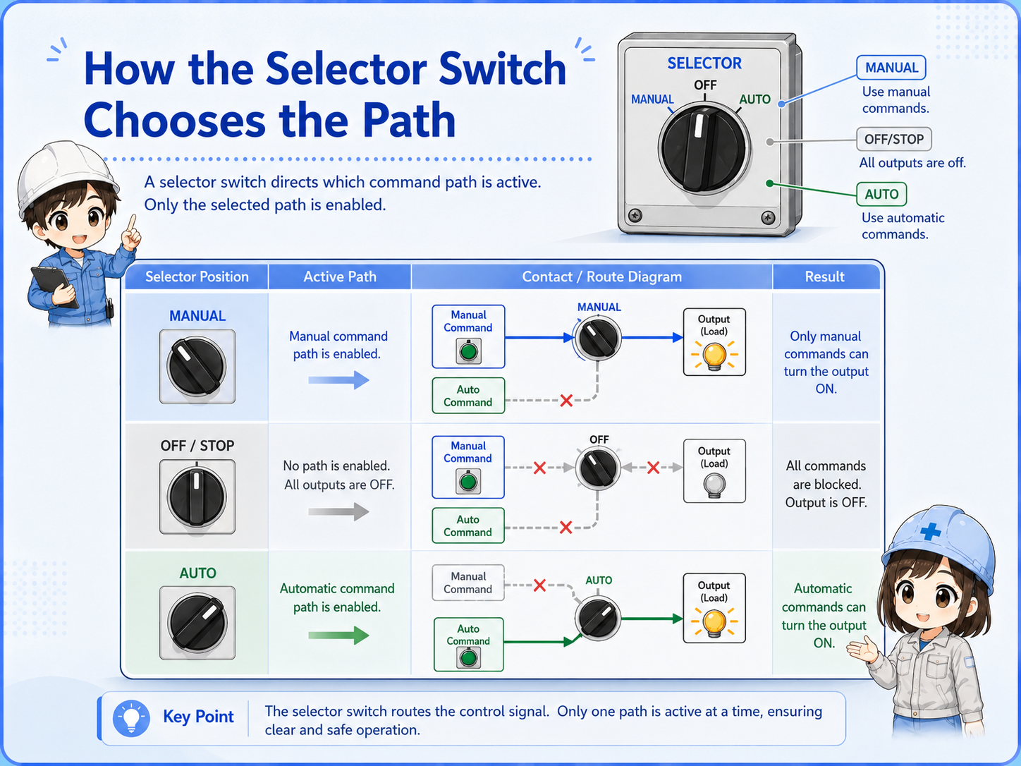
| Position | Typical meaning | Beginner check |
|---|---|---|
| Manual | Allows local or panel command. | Confirm the manual command is wired through the Manual contact. |
| Auto | Allows sequence or PLC command. | Confirm the auto signal reaches the output only in Auto mode. |
| Stop / OFF | Blocks both command paths in a simple circuit. | Confirm the output is disabled in the center/off position. |
Priority, stop conditions, and interlocks
A good selector circuit also preserves common stop and interlock conditions. Emergency stop, overload trip, guard switch, limit switch, or ready conditions may need to block the output in both Manual and Auto.
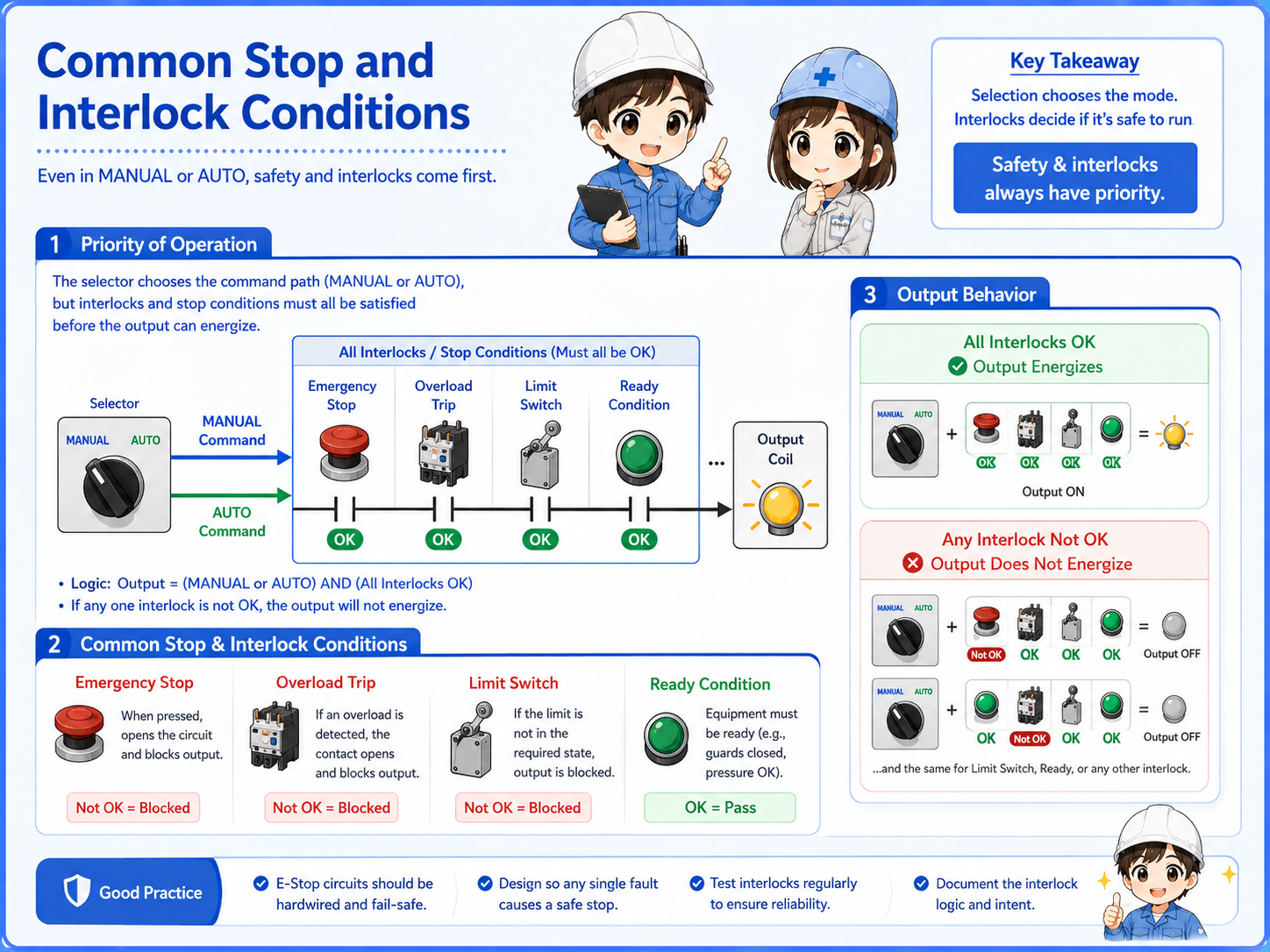
Manual mode does not mean safety can be ignored.
Which conditions remain active must be decided from the actual machine design, electrical drawing, and official documentation.
A simple ladder-style way to read it
In a beginner-friendly view, you can imagine two branches. One branch is valid in Manual mode. The other branch is valid in Auto mode. Both branches join before the final output coil.
This is only a conceptual example. Real circuits may include self-hold contacts, reset conditions, lamps, alarms, PLC inputs, safety devices, or manufacturer-specific terminal names.
Always check the actual drawing.
Labels such as HAND, MAN, AUTO, LOCAL, REMOTE, RUN, and START may be used differently by each panel or machine.
Field checks when Manual or Auto does not work
When the output does not operate in one mode, separate the problem into selector position, command input, common stop/interlock, and output side.
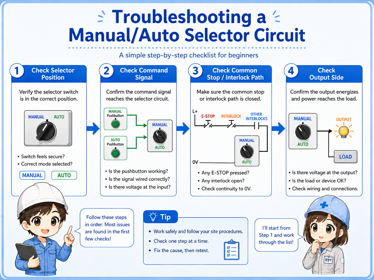

If Manual works but Auto does not, the final output may be fine. Follow the Auto command path before replacing parts.

So I should compare the selected path, command signal, common interlock, and output side step by step.
Selector contact
Confirm which contact closes in each position.
Command signal
Check whether the manual or auto command is actually present.
Common stop path
Verify trip, stop, limit, and permissive conditions.
Output side
Confirm the final relay, solenoid, lamp, or PLC output.
Summary: Manual/Auto is a command-path selector
A Manual/Auto selector circuit separates two command sources and allows only the selected path to control one output.
The safest way to read it is to follow the signal path: selector position, manual or auto command, common stop/interlock conditions, and final output.
Field-friendly way to remember it
Manual/Auto is not just a switch label. It is a rule for which command path is allowed to reach the output.