What is a proximity sensor?
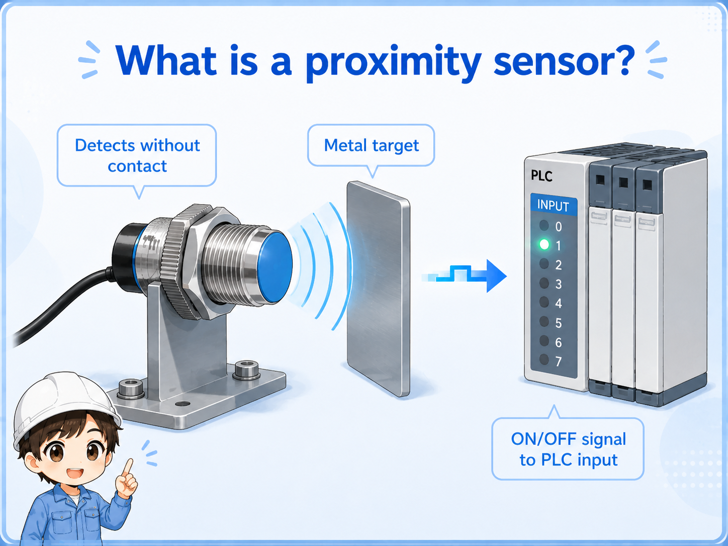
A proximity sensor detects a target without touching it and sends an ON/OFF signal to a control circuit or PLC input.
In many machines, a proximity sensor is used to detect a metal target such as a dog plate, bracket, machine part, or workpiece. Unlike a mechanical switch, it does not need the object to physically press an actuator.
This makes it useful for repeated machine movement because there is less mechanical wear. However, the detection distance is short, and stable detection depends on the sensor type, target material, mounting position, and wiring.

A proximity sensor is simple to use, but it is not magic. The target material, distance, and mounting condition all affect detection.

So before replacing the sensor, I should check the LED, target distance, wiring, and PLC input monitor in order.
What does a proximity sensor detect?
Many common proximity sensors used in factory control are inductive sensors, which are mainly used for metal targets.
A beginner mistake is to think that every non-contact sensor detects every kind of material. In practice, an inductive proximity sensor is usually chosen for metal detection, and the stable distance depends on the sensor size, target size, material, and mounting method.
Iron, stainless steel, and aluminum may not behave exactly the same. If the target is small, thin, angled, or far from the sensor face, the detection margin can become unstable.
| Item | Practical point |
|---|---|
| Target material | Many inductive proximity sensors are mainly used for metal targets. |
| Detection distance | The distance is usually short and affected by sensor size and target material. |
| Mounting | Flush and non-flush sensor types have different mounting requirements. |
| Output | The sensor output is read by a PLC input as an ON/OFF signal. |
Check the actual model
Detection distance and suitable target conditions vary by manufacturer and model. Use this article as a basic idea, and check the official manual for the actual sensor being used.
Proximity sensor vs limit switch
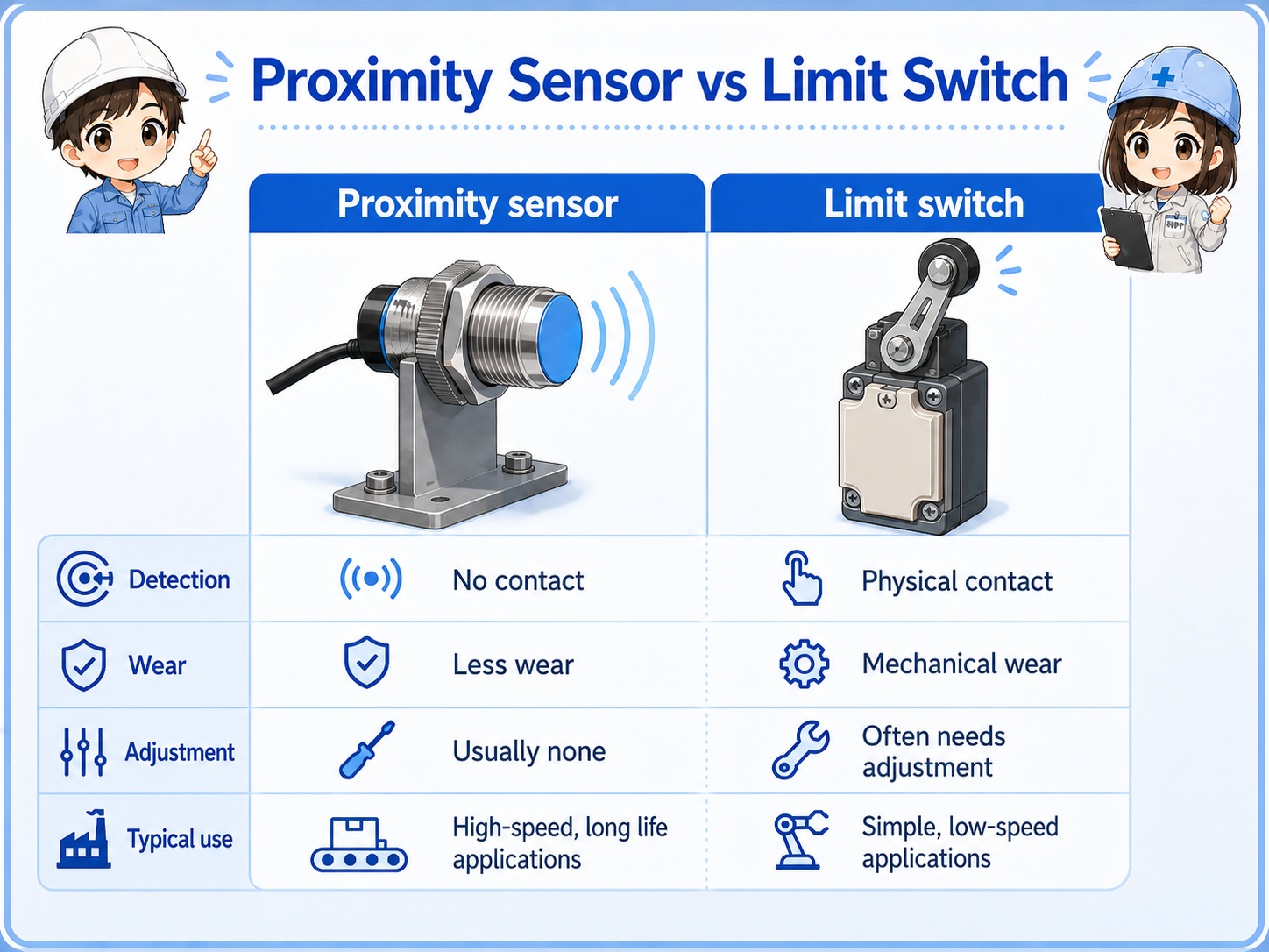
A limit switch detects by contact. A proximity sensor detects without contact.
A limit switch is mechanically easy to understand because the object physically presses the switch. A proximity sensor has less mechanical wear because there is no contact, but it needs the correct sensing distance and target condition.
| Item | Proximity sensor | Limit switch |
|---|---|---|
| Detection method | Detects without physical contact. | Detects when an object presses the actuator. |
| Wear | Less mechanical wear at the detection point. | Mechanical parts can wear or bend over time. |
| Adjustment | Requires distance and target condition checks. | Requires mechanical position and actuator checks. |
| Typical use | Machine position, metal dog plates, workpiece presence. | End position detection, door position, mechanical contact points. |
Signal flow from proximity sensor to PLC input
The PLC does not directly “see” the target. It reads the electrical output from the sensor.
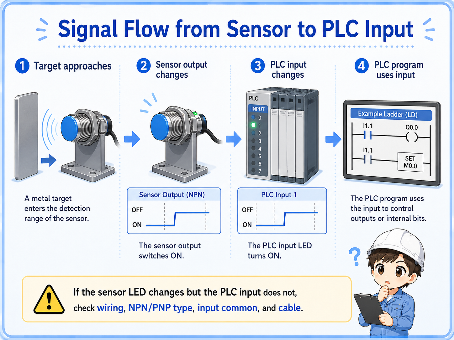
The basic flow is simple: the target approaches the sensor, the sensor output changes, the PLC input turns ON or OFF, and the PLC program uses that input condition.
1. Target approaches
A metal target moves into the sensor detection range.
2. Sensor output changes
The sensor changes its output according to the detected state.
3. PLC input changes
The PLC input module reads the sensor output as an input signal.
Important separation
Sensor LED changing means the sensor side may be detecting. PLC input changing means the electrical signal is reaching the PLC correctly. Always compare both.
Field checks before replacing the sensor
Do not replace the sensor immediately. First check whether the detection condition and the electrical signal are both correct.
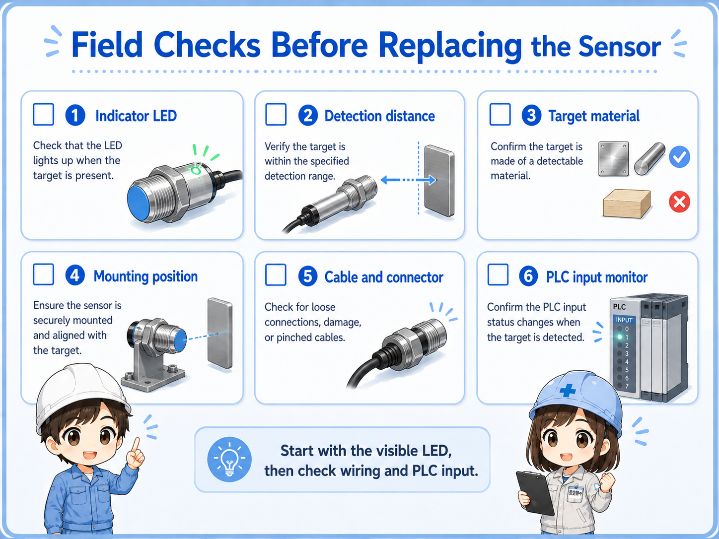
1. Indicator LED
Move the target slowly and confirm whether the sensor LED changes at the expected position.
2. Detection distance
Check whether the target is inside the stable detection range, not just at the edge.
3. Target material
Confirm that the target material and size are suitable for the sensor type.
4. Mounting position
Look for loose brackets, vibration, angle changes, or surrounding metal near the sensor.
5. Cable and connector
Check for broken wires, loose connectors, oil damage, or intermittent cable movement.
6. PLC input monitor
Compare the sensor LED with the PLC input monitor to separate sensor detection from wiring issues.
Good field habit
Take a photo of the sensor position before adjustment. If the bracket or sensor distance is changed without record, the original condition becomes harder to reproduce.
Common trouble patterns
Write down whether the sensor never turns ON, stays ON, changes but does not reach the PLC, or works only sometimes.
| Symptom | Likely area | First check |
|---|---|---|
| Sensor does not turn ON | Distance, target material, power supply, sensor type. | Move the target slowly and watch the sensor LED. |
| Sensor stays ON | Wrong position, surrounding metal, wiring issue. | Remove the target and check whether the LED changes. |
| LED changes but PLC input does not | Wiring, NPN/PNP mismatch, input common, broken cable. | Check voltage at the PLC input terminal and compare with the input monitor. |
| Unstable detection | Vibration, marginal distance, loose bracket, metal chips. | Clean the area and secure the mounting position. |
Do not change too many things at once
If you change distance, bracket angle, sensor type, and wiring at the same time, it becomes difficult to know what solved the problem. Change and confirm one point at a time.
Summary
Proximity sensors are common in electrical control because they detect without physical contact. They are especially useful for machine position and metal target detection.
The key is to separate physical detection from electrical signal checking. Start from the sensor LED, then compare it with the PLC input monitor. If the LED changes but the PLC input does not, look at wiring, NPN/PNP type, input common, cable condition, and the input module.
Final takeaway
A proximity sensor is easy to understand when you think in two steps: “Can the sensor detect the target?” and “Does that signal reach the PLC?”
Related articles
Read these next to connect proximity sensors with PLC inputs and sensor output wiring.