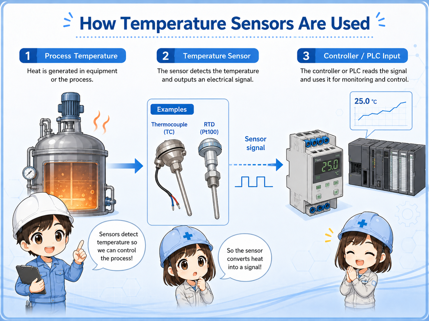
1. Basic role: converting heat into a control signal
A temperature sensor does not simply “send temperature.” It creates a signal that must be interpreted by the correct input device.
In industrial control, a temperature sensor is used to monitor heater temperature, machine temperature, process temperature, panel temperature, or fluid temperature. The sensor itself is only one part of the measurement path. The signal is read by a temperature controller, transmitter, or PLC temperature input module.
The important beginner point is this: the sensor type and the input setting must match. A thermocouple input, RTD input, analog input, and temperature transmitter input are not interchangeable without checking the specification.

When the displayed temperature is strange, do not look only at the PLC value. First check what type of sensor is installed.

So thermocouple and Pt100 wiring should not be treated as the same kind of signal.
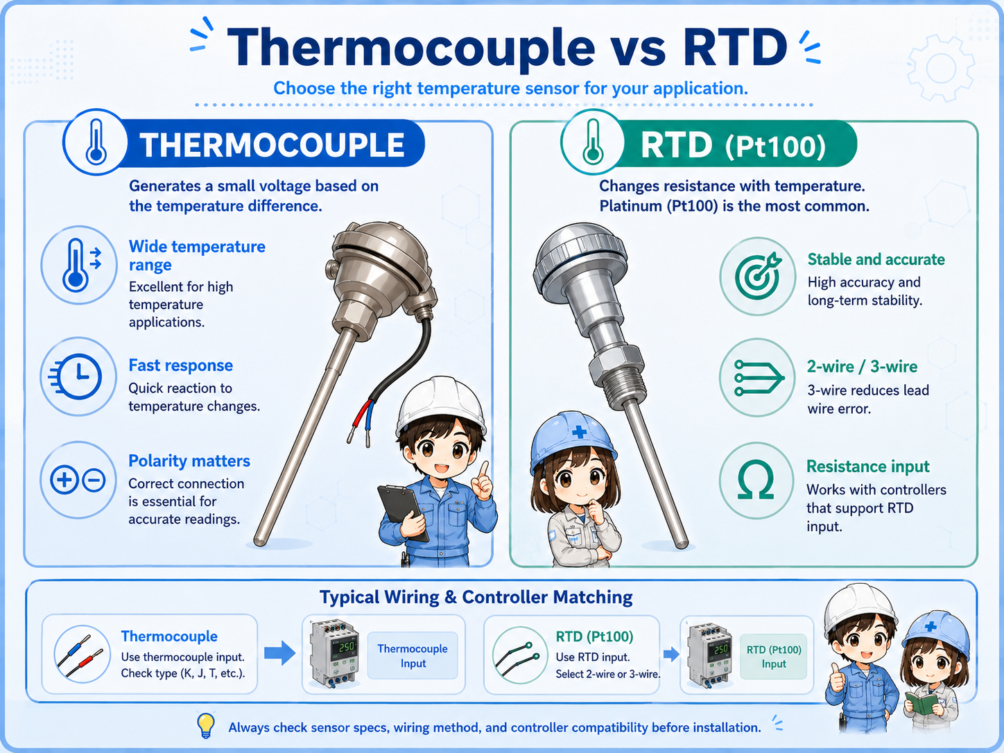
2. Thermocouple and RTD: the two common types
Thermocouples and RTDs measure temperature in different ways, so the input device must be configured correctly.
A thermocouple uses two different metal conductors and produces a small voltage related to temperature difference. It is often used for higher-temperature or fast-response applications. The exact type, such as K, J, or T, must match the controller or input module setting.
An RTD, such as Pt100, uses the change in electrical resistance with temperature. RTDs are commonly used when stable and repeatable measurement is important. Two-wire, three-wire, and four-wire wiring methods affect how lead-wire resistance is handled.
| Type | Basic principle | Typical check point |
|---|---|---|
| Thermocouple | Small voltage is generated from two dissimilar metals and temperature difference. | Check thermocouple type, polarity, extension wire, and input setting. |
| RTD / Pt100 | Resistance changes with temperature and the input device measures that resistance. | Check 2-wire / 3-wire / 4-wire wiring, lead resistance, and input setting. |
| Transmitter output | A transmitter converts the sensor signal into a standard analog signal. | Check transmitter power, range setting, and analog input type. |
Manual check matters
Sensor type, usable temperature range, polarity, terminal names, and wiring method vary by product. Confirm the actual model manual and machine drawing before changing wiring or settings.
3. Wiring and input setting must match
Wrong sensor selection or wrong input setting can make the displayed value incorrect even if the wiring is physically connected.
Temperature inputs are more sensitive to wiring rules than simple ON/OFF inputs. Thermocouple wiring requires attention to polarity and proper extension or compensating cable. RTD wiring requires attention to the number of wires and terminal assignment.
If the controller or PLC input is configured for the wrong sensor type, the value may be far from the real temperature, jump unexpectedly, or show an error. In field troubleshooting, compare the sensor installed on the machine with the parameter setting in the controller or input module.
Sensor type
Confirm whether the installed sensor is thermocouple, RTD, or transmitter output.
Input setting
Check whether the controller or PLC module is set to the same sensor type.
Terminal assignment
Check polarity, RTD wire count, common terminal, and loose screws.
Cable condition
Check broken wires, wrong extension cable, shielding, routing, and noise influence.
4. Signal flow to a temperature controller or PLC
The temperature value is created by the whole measurement chain, not by the sensor alone.
Some systems connect the sensor directly to a temperature controller. Other systems connect the sensor to a PLC temperature input module. In other cases, a transmitter converts the temperature measurement into a 4–20 mA or voltage signal before the PLC reads it as an analog input.
Because there are several possible paths, always trace the actual system before deciding where the fault is. A wrong display can come from the sensor, wiring, controller setting, transmitter range, analog scaling, or PLC program display.
1. Sensor
Thermocouple, RTD, or transmitter receives the temperature condition.
2. Input device
Temperature controller, PLC temperature module, or analog input reads the signal.
3. Control logic
The value is used for alarm, heater control, monitoring, or interlock logic.
Do not skip scaling checks
If a transmitter or analog input is used, the displayed value depends on the configured range and scaling. Check the sensor side and the scaling side separately.
5. Common mistakes
Temperature sensor faults are often caused by mismatch, polarity, wiring, or settings rather than the sensor element alone.
- Using a thermocouple input setting for an RTD sensor, or the opposite.
- Mixing thermocouple type settings, such as selecting the wrong type in the controller.
- Reversing thermocouple polarity and getting a value that moves in the wrong direction.
- Using normal copper cable where the system requires proper thermocouple extension or compensating cable.
- Miswiring a three-wire RTD and creating unstable or inaccurate readings.
- Changing PLC scaling before checking the real input device and wiring.
Do not force a value just to clear an alarm
If a temperature value is used for machine protection or heater control, forcing the value can create a dangerous condition. Find the actual cause and follow site procedures.
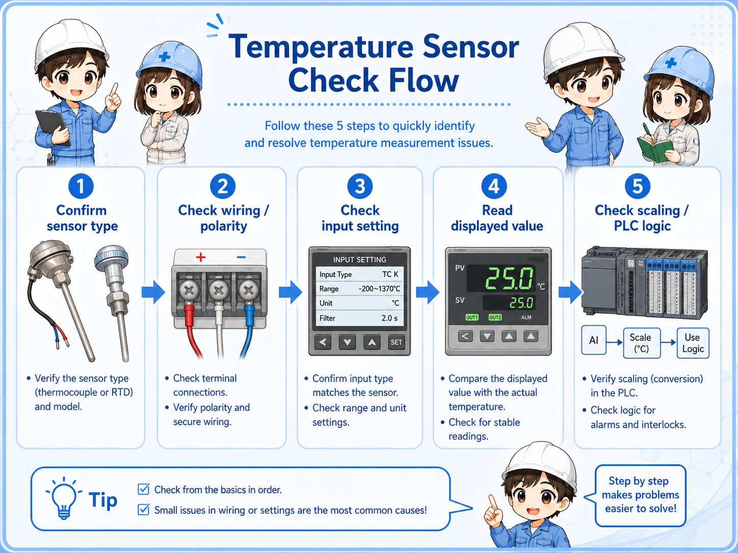
6. Field check flow
A stable troubleshooting order is sensor type → wiring → input setting → displayed value → control logic.
When a temperature value is wrong, first confirm what sensor is physically installed. Then check the wiring and terminal condition. After that, compare the controller or PLC module setting with the sensor type. Only after these checks should you review scaling and program display logic.
1. Identify the sensor
Read the label, drawing, or part number. Confirm thermocouple, RTD, or transmitter.
2. Check wiring
Inspect polarity, terminal screws, wire count, cable type, and shielding.
3. Check settings
Compare sensor type and range settings in the controller or PLC module.
4. Check display / logic
Confirm scaling, alarm setpoints, and whether the PLC display uses the correct address.
7. Quick summary
Temperature sensor troubleshooting becomes easier when you separate sensor type, wiring, input setting, and scaling.
A temperature sensor is part of a measurement chain. Thermocouples, RTDs, and transmitters each have different signal behavior. Before replacing a sensor or changing a program, confirm the installed sensor type, the wiring method, the input setting, and the displayed value path.
Remember this
For real machines, always check the actual device manual, wiring diagram, and site procedure. Temperature input terminals and settings differ by model.
Related articles
These English articles are useful next steps after learning temperature sensors.