What is a current transformer?
A current transformer detects current flowing in a conductor and converts it into a smaller signal for measurement or monitoring.
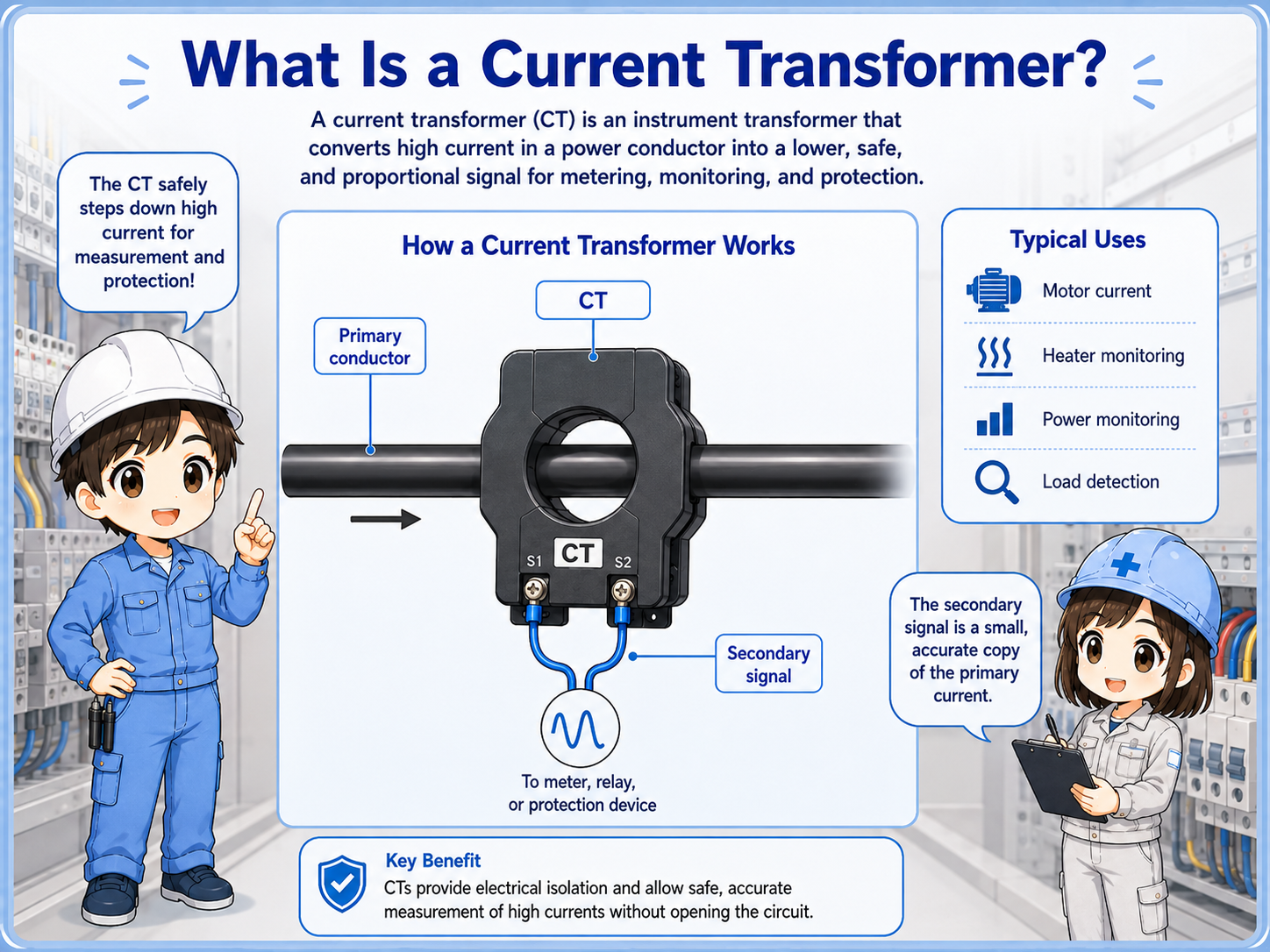
A current transformer, or CT, is placed around a power conductor. When current flows through that conductor, the CT produces a proportional output that can be used by a meter, power monitor, PLC input device, or protection equipment.
The key idea is simple: instead of sending the full motor or heater current directly into a control device, the CT provides a smaller and easier-to-handle signal. This makes current monitoring practical inside control panels.
Think of a CT as an indirect current detector
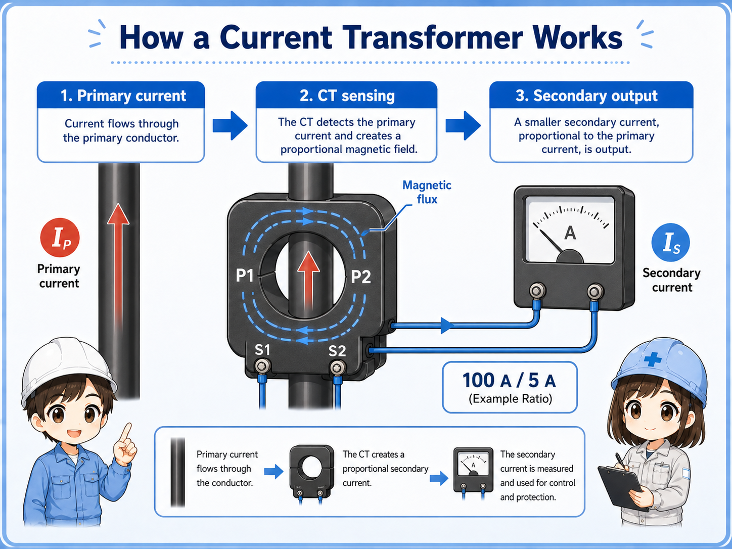
The load current flows through the primary conductor. The CT senses that current and sends a smaller secondary signal to the monitoring device.
Why measure current?
Current measurement helps confirm load operation, detect abnormal conditions, and monitor machine behavior.
In field work, current is often checked to confirm whether a motor, heater, pump, fan, or other load is actually operating. A PLC may use current detection to judge whether the expected load current is present.
Current monitoring can also help find abnormal conditions, such as overload, underload, broken heater circuits, idle running, mechanical load changes, or unexpected operation timing.

If a motor command is ON, current monitoring can help confirm whether the motor is actually drawing current. That is different from only checking the output signal.

So the CT helps us look at the real load side, not only the command side.
CT ratio and output signal
A CT ratio shows how the primary current is converted into a smaller secondary output.
CT ratio shows how the primary current relates to the secondary output. For example, a 100 A / 5 A CT is designed so that the secondary output corresponds to the primary current according to that ratio. The meter, power monitor, relay, or controller setting must match the actual CT ratio. Not all CTs use the same secondary output, so always check the CT nameplate, wiring diagram, and device manual.
| Term | Meaning | Field note |
|---|---|---|
| Primary side | The conductor carrying the actual load current. | Usually the wire passing through the CT window. |
| Secondary side | The output from the CT or current sensor. | Connects to a meter, monitor, relay, or input device. |
| Ratio | The relationship between primary current and secondary output. | Must match the measuring device and design. |
Common CT and current sensor types
Different current sensors are used depending on panel layout, load current, and monitoring purpose.
Ring-type CT
A conductor passes through the center. Common in panels for metering or monitoring.
Split-core or clamp type
Can be opened and attached around an existing conductor without removing the wire.
Current sensor module
May output voltage, current, pulse, or digital signals depending on the device.
Power monitor input
Often uses CTs to monitor current, power, energy, or load state.
Always check the model and wiring diagram
CT output type, ratio, polarity, and allowable connection method vary by product. Do not assume all CTs are wired the same way.
Field checks for current transformers
Check conductor placement, direction, ratio, wiring, terminal condition, and the actual load behavior.

Check the conductor
Confirm that the correct phase or load wire passes through the CT.
Check direction
Look for markings such as K/L, P1/P2, source/load, or arrow direction.
Check ratio and device setting
The CT ratio must match the meter, monitor, or controller setting.
Check wiring condition
Loose terminals, wrong polarity, or broken secondary wiring can cause incorrect readings.
Important safety note about CT secondary circuits
Some CT secondary circuits must not be opened while current is flowing. Opening the secondary circuit of some current transformers can create dangerous voltage or damage equipment. Do not disconnect CT wiring under load unless the product manual and qualified electrical procedure allow it. Follow the product manual and qualified electrical procedures before touching CT wiring.
Common mistakes
Most mistakes come from wrong conductor placement, wrong ratio, or assuming all CTs behave the same.
- Passing multiple conductors through the CT and canceling the measured current.
- Installing the CT in the wrong direction for the measuring device.
- Using a CT ratio that does not match the monitor setting.
- Checking only the PLC signal and forgetting to check the actual load current.
- Opening or changing CT secondary wiring without understanding the safety requirement.
One conductor is usually the basic idea
For a simple load-current check, the CT usually measures one conductor. If all outgoing and returning conductors pass through together, the magnetic fields can cancel.
Summary: CTs make current monitoring practical
A current transformer detects load current indirectly and sends a smaller signal to a measuring or monitoring device. This is useful for motor current, heater current, load monitoring, and abnormal condition detection.
In the field, check the conductor, CT direction, ratio, wiring, terminal condition, and the actual machine behavior together. CTs are simple in concept, but the details matter for safe and reliable current measurement.