What is an analog input?
An analog input is a PLC input that reads a continuously changing value.
A normal ON/OFF input tells the PLC whether a signal is simply ON or OFF. An analog input is different. It reads a signal that changes gradually, such as pressure, temperature, level, or flow.
In control panels, analog input modules are often connected to transmitters and sensors that output signals such as 0-10V or 4-20mA. The PLC then converts that signal into a number that can be used in the program or displayed on an HMI.
The basic idea
Digital input answers “ON or OFF?” Analog input answers “How much?” That difference is the first point to understand.

With an ON/OFF input, the PLC only knows whether the signal is present. With analog input, the PLC reads a changing value.

So analog input is used when the PLC needs a number, like pressure or temperature?
Exactly. The signal is converted into a value the PLC can calculate, compare, or display.
Digital input vs analog input
Digital inputs read states. Analog inputs read amounts.
| Item | Digital input | Analog input |
|---|---|---|
| Main meaning | ON or OFF | Changing value |
| Typical devices | Push button, limit switch, proximity sensor, photoelectric sensor | Pressure transmitter, temperature transmitter, level sensor, flow sensor |
| PLC data | Bit value such as ON/OFF, 1/0, TRUE/FALSE | Numeric value such as raw count, pressure, temperature, level, or flow |
| Common field signals | 24V DC ON/OFF signal | 0-10V, 1-5V, 4-20mA, 0-20mA |
Simple way to remember
If the PLC only needs to know whether a device is ON, it is usually digital. If the PLC needs to know how high, how hot, how much, or how fast, it is usually analog.
0-10V and 4-20mA signal basics
The two signals beginners often meet first are 0-10V voltage signals and 4-20mA current signals.
A 0-10V signal changes its voltage according to the measured value. A 4-20mA signal changes its current according to the measured value. Both are used to send analog information from a sensor or transmitter to a PLC analog input module.
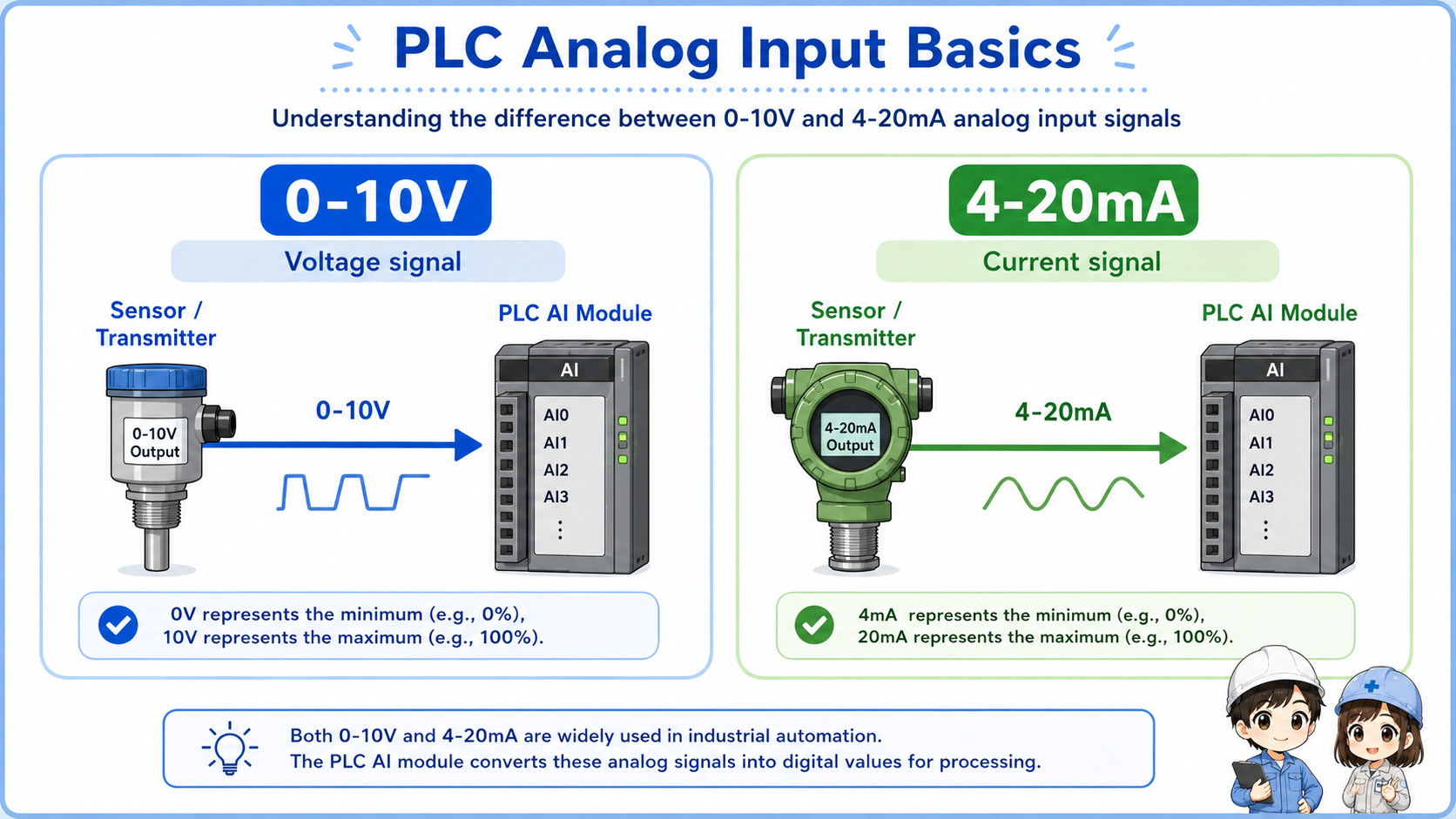
0-10V signal
The voltage changes between 0V and 10V. It is easy to understand with a voltmeter.
4-20mA signal
The current changes between 4mA and 20mA. It is common in industrial transmitters.
Input range setting
The PLC analog input module must be set for the correct signal type.
Wiring difference
Voltage and current input wiring can be different, so check the module manual and drawing.
Why 4-20mA starts at 4mA
In many systems, 4mA represents the lower end of the measurement range. If the signal is 0mA, it may indicate a broken wire, missing power, or signal failure rather than a real zero measurement.
Scaling: converting the signal into a usable value
The PLC usually receives a raw analog value first, then converts it into an engineering value.
For example, a pressure transmitter may output 4-20mA for 0-1.0 MPa. The PLC analog input reads the signal and converts it into a value that represents pressure. This conversion is often called scaling.
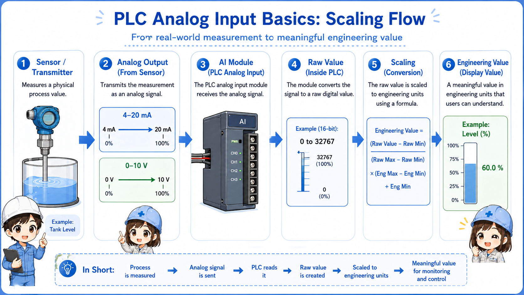
1. Sensor measures
A device measures pressure, temperature, level, or flow.
2. Signal changes
The transmitter outputs 0-10V or 4-20mA.
3. AI module reads
The PLC analog input module reads the signal.
4. PLC scales
The raw value is converted into an engineering value.
5. Program uses it
The PLC compares, displays, records, or controls using the value.
| Example | Low signal | High signal | Meaning after scaling |
|---|---|---|---|
| Pressure transmitter | 4mA | 20mA | 0 to 1.0 MPa |
| Level sensor | 0V | 10V | 0 to 100% |
| Temperature transmitter | 4mA | 20mA | 0 to 200°C |
Important point
The analog signal and the displayed value are not always the same thing. The PLC may read a raw value first, then convert it by scaling.
Field check points for analog input problems
When the analog value is wrong, check the sensor, wiring, input range, and scaling instead of guessing one part.
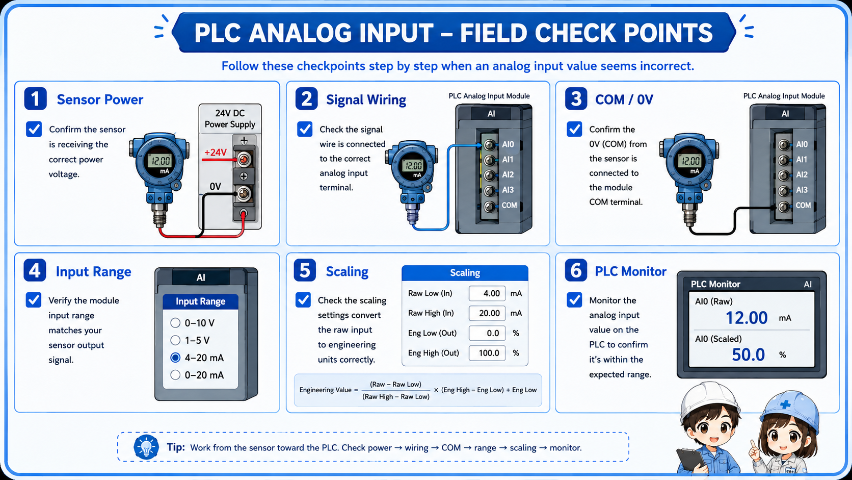
Sensor or transmitter power
Check whether the device has the correct supply voltage and is operating normally.
Signal wiring
Check polarity, terminal number, shield, broken wire, and loose terminal screws.
Input range
Confirm that the PLC analog input is set for voltage or current as required.
Scaling and monitor value
Compare the field signal, raw PLC value, scaled value, and HMI display.
Do not change analog parameters without checking the drawing
Changing input range or scaling settings can affect displayed values and machine behavior. Confirm the drawing, device range, and program meaning first.
Common mistakes with analog inputs
Many analog input problems come from range mismatch, wiring errors, or misunderstanding raw values.
| Mistake | Why it causes trouble | Better check |
|---|---|---|
| Voltage/current range mismatch | A 4-20mA signal connected to a voltage input may not read correctly. | Check the module setting and wiring terminals. |
| Ignoring scaling | The PLC raw value may not directly equal the real pressure or temperature. | Check the scaling range and engineering units. |
| Checking only the HMI value | The displayed value may already include program calculation or formatting. | Compare field signal, raw value, scaled value, and display. |
| Forgetting the common or 0V side | A missing reference line can make the analog signal unstable or wrong. | Check signal line, common, 0V, and shield treatment as shown on the drawing. |
Beginner-friendly rule
When an analog value looks wrong, do not ask only “is the sensor bad?” Ask “is the field signal correct, and is the PLC converting it correctly?”
Safety notes before checking analog input wiring
Analog input wiring may be low voltage, but it is still part of a control panel and process control system.
Always follow the site rules and drawings. Do not short terminals with meter probes, and do not change wiring or parameters while the machine is operating unless you are qualified and permitted to do so.
If the analog value is used for pressure, temperature, level, or flow control, an incorrect value can affect machine operation. Treat signal checks and parameter changes carefully.
Analog values can affect control behavior
A wrong analog value may cause incorrect alarms, bad control decisions, or unsafe machine conditions. Check the system impact before making changes.