What is an upper and lower limit circuit?
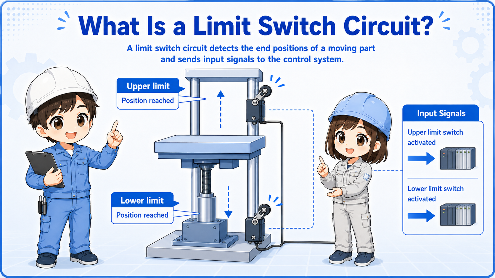
It is a basic protection circuit that prevents a moving part from going beyond its allowed range.
An upper and lower limit circuit uses limit switches to stop movement at the end positions. In vertical movement, the upper limit stops upward movement and the lower limit stops downward movement.
The same idea is also used for forward and reverse movement. One limit switch blocks further movement in one direction, while allowing movement back in the opposite direction.

Think of the upper and lower limits as the end points of safe travel. They do not just detect position; they are also used to prevent movement in the wrong direction.

So if the upper limit is already ON, I should not allow the machine to move farther upward, but moving downward may still be allowed.
Limit switches are not always safety devices
Some limit switches are used for normal control, while safety-related stopping may require safety-rated devices and circuits. Always follow the actual machine documentation and site rules.
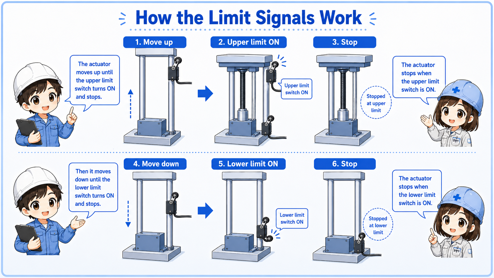
Limit switch flow
Each limit switch usually blocks movement farther into that limit, while allowing movement away from it.
When the moving part reaches the upper limit, the upper direction should stop. The reverse direction may still be allowed so the mechanism can move away from the limit.
| Position condition | Movement to stop | Movement often allowed | Field image |
|---|---|---|---|
| Upper limit reached | Upward or forward movement | Downward or reverse movement | Move away from the upper end position. |
| Lower limit reached | Downward or reverse movement | Upward or forward movement | Move away from the lower end position. |
Beginner takeaway
Do not read a limit switch as simply “stop everything.” Read it together with the direction command.
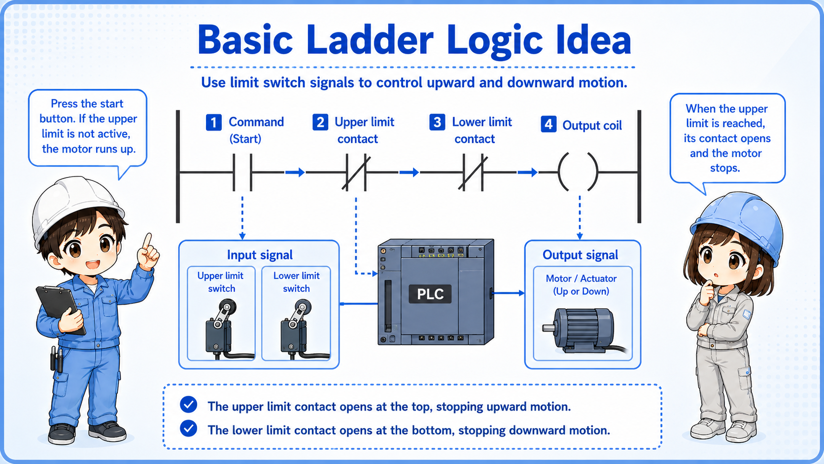
Basic ladder logic idea
A limit switch is often placed as a condition that prevents output in one movement direction.
In ladder logic, an upper limit condition may be inserted into the rung for the upward output. If the upper limit is active, the upward output is blocked.
The lower limit condition is used in the opposite direction. If the lower limit is active, the downward output is blocked.
Contact type depends on the design
Some circuits use normally closed limit switch contacts for fail-safe behavior, while others use PLC input logic and internal conditions. Do not assume the contact type only from the name. Check the drawing and PLC monitor.
Relationship with interlocks
Upper and lower limits are often part of the interlock conditions for movement outputs.
An interlock prevents an unsafe or conflicting operation. In a movement circuit, the limit switch can be one of the conditions that prevents a direction output.
For example, an upward command may require “not at upper limit” and “no stop condition” before the output turns ON.
| Item | Basic role | How to read it |
|---|---|---|
| Direction command | Requests upward, downward, forward, or reverse movement. | Check whether the operator, PLC step, or auto sequence is requesting movement. |
| Limit switch | Detects that an end position has been reached. | Check whether that end position should block the requested direction. |
| Interlock | Combines permission and stop conditions. | Check all blocking conditions, not only the limit switch. |
Read from the output backward
When an output does not turn ON, trace backward from the output coil and check which condition is blocking it.
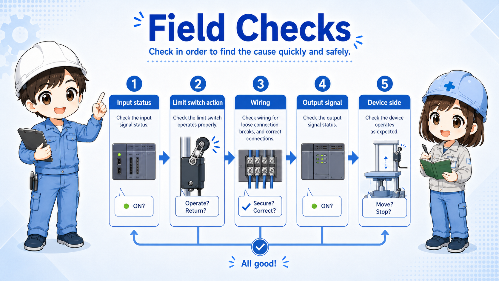
Field checks when the machine does not move
Check the command, limit switch input, interlock conditions, output, wiring, and device side in order.
1. Movement command
Confirm whether the PLC or operator is actually requesting upward, downward, forward, or reverse movement.
2. Limit switch input
Check the PLC input monitor for the upper and lower limit switches.
3. Physical switch state
Check whether the switch is actually pressed, stuck, misaligned, or damaged.
4. Interlock logic
Check other stop, alarm, mode, permission, and safety-related conditions.
5. Output and wiring
Confirm the output coil, output terminal, relay, valve, motor starter, and common wiring.
6. Mechanical side
Check whether the mechanism is jammed, overloaded, or already at the end of travel.
Do not bypass a limit switch casually
A limit switch may be preventing overtravel or damage. Bypassing it without understanding the machine condition can cause collision, equipment damage, or a hazardous situation.
Summary
An upper and lower limit circuit prevents a moving part from going beyond its allowed range. The upper limit blocks movement farther upward or forward, and the lower limit blocks movement farther downward or reverse.
In the field, read the limit switch together with the movement direction. The same limit input may block one direction while allowing the opposite direction so the machine can move away from the limit.
Final takeaway
Limit circuits are not just input checks. They are direction-based stop conditions. Always read command, limit input, interlock, output, and mechanical position as one set.
Related articles
Read these next to connect limit circuits with basic ladder logic and movement control.