Good fit for
- Beginners learning alarm and buzzer circuits.
- People who want to understand PLC output and buzzer wiring.
- Technicians checking why a buzzer does not sound or stop.
A buzzer circuit sounds an audible alarm when an abnormal condition occurs. This guide explains the basic idea, PLC output wiring, hold and reset logic, and field checks.
A buzzer circuit gives an audible warning when a machine or control panel detects an abnormal condition.
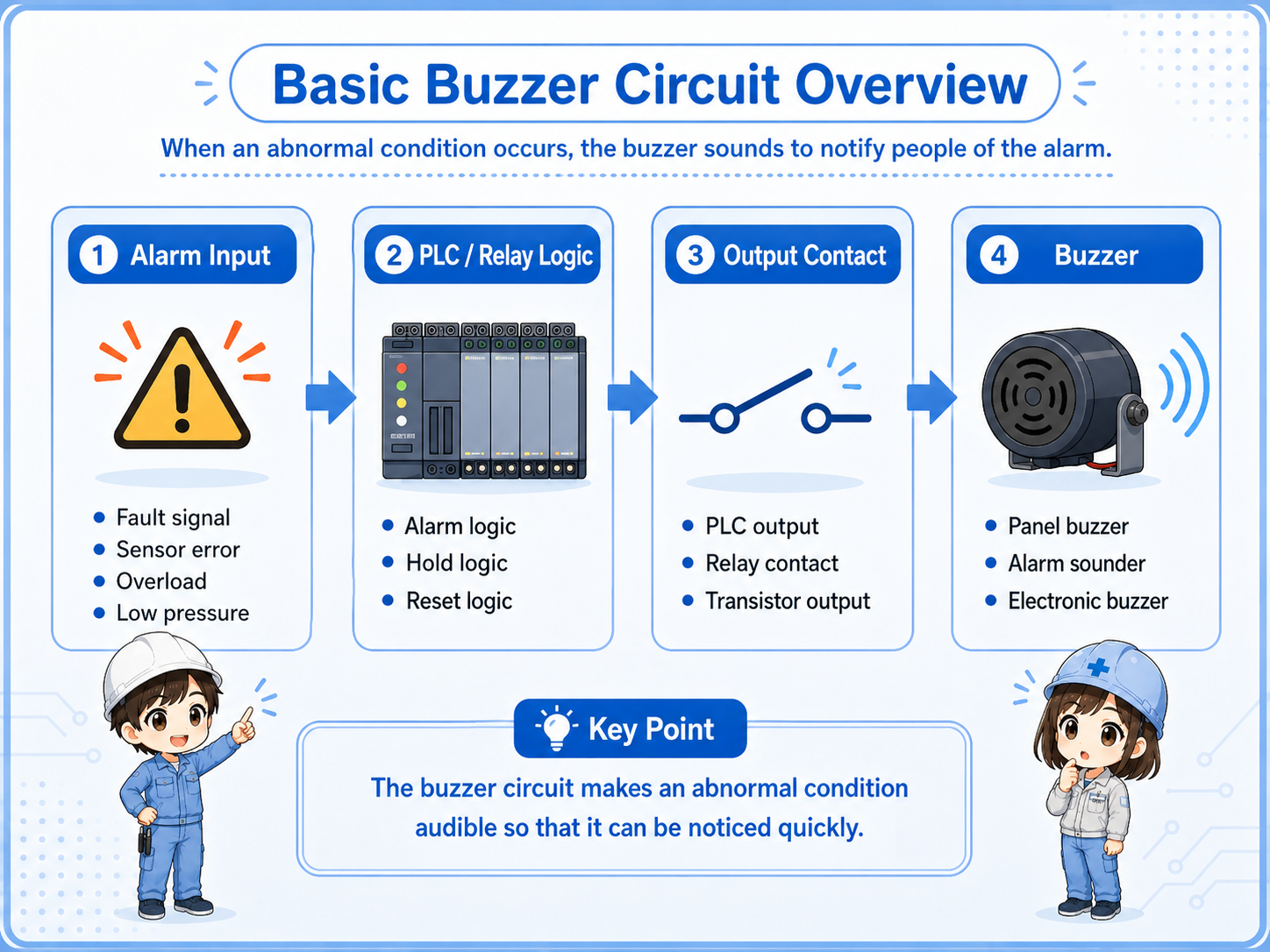
A buzzer circuit is a basic alarm circuit used to notify people that something needs attention. In a control panel, the buzzer is usually driven by a PLC output, relay contact, or alarm circuit when an abnormal condition turns ON.
Typical examples include overload alarms, emergency-related warnings, sensor errors, low air pressure, inverter faults, or process abnormalities. The buzzer does not fix the problem by itself. Its role is to make the abnormal condition noticeable.
A lamp shows the alarm visually. A buzzer adds sound, so people can notice the alarm even when they are not looking at the panel.
Separate the alarm condition, control logic, output device, and buzzer load.
| Part | Role | Field image |
|---|---|---|
| Alarm input | The condition that tells the circuit something abnormal happened. | Fault signal, pressure switch, overload contact, sensor error. |
| PLC or relay logic | Decides when the buzzer should sound, hold, or stop. | Alarm rung, hold circuit, reset condition. |
| Output contact | Switches power to the buzzer or energizes a relay that drives it. | PLC output, relay contact, transistor output, relay output. |
| Buzzer | The sounder load that produces the audible alarm. | Panel buzzer, alarm sounder, electronic buzzer. |
Buzzer voltage, current, polarity, and PLC output capacity depend on the actual device. Always check the official manuals and nameplates before wiring or replacing parts.
For beginners, focus on the condition that turns the buzzer ON and the condition that stops it.
The simplest idea is: when an alarm condition is ON, the buzzer output turns ON. In many real panels, the buzzer may also be held until an operator presses a reset or acknowledge button.
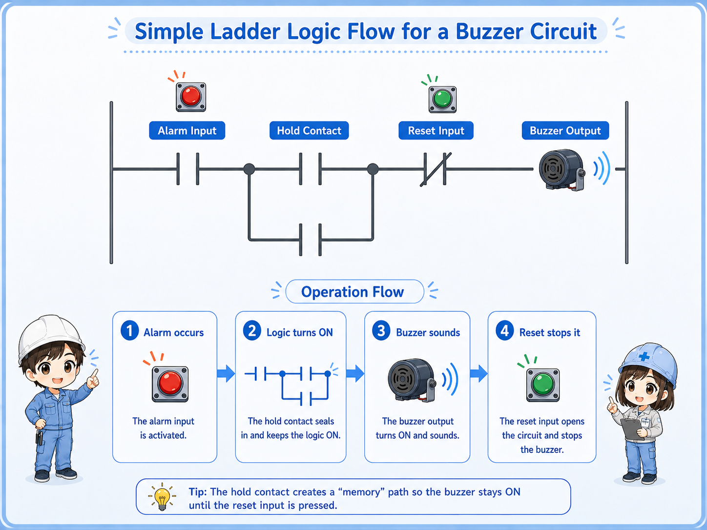
An abnormal input or fault condition turns ON.
The PLC or relay circuit detects the alarm condition.
The output device supplies power to the buzzer.
A reset or acknowledge condition turns the buzzer OFF.
If a reset button can silence a buzzer while the abnormal condition is still active, the alarm may be missed. In real equipment, design the alarm behavior according to the machine risk, operation rules, and official documentation.
A momentary fault may disappear quickly, but the operator still needs to know it happened.
Some alarm inputs stay ON while the problem exists. Others may turn ON only briefly. If the buzzer only follows the input directly, the sound may stop before anyone notices it.
For that reason, buzzer circuits often use hold logic. Once the alarm occurs, the buzzer or alarm state stays ON until an operator acknowledges or resets it.
The buzzer sounds only while the alarm input is ON. Simple, but easy to miss if the signal is short.
The buzzer remains active after the alarm occurs until reset or acknowledge logic clears it.
An acknowledge button may silence the sound while leaving a visual alarm active.
A reset condition usually clears the alarm only when the abnormal condition has been removed.
In some machines, silencing the buzzer and clearing the alarm are different actions. This prevents the sound from continuing forever while still keeping the alarm visible.
Many buzzer problems come from output wiring, reset logic, or misunderstanding the alarm condition.
| Symptom | Likely point to check | Basic idea |
|---|---|---|
| Buzzer does not sound | Alarm input, PLC output, fuse, power supply, buzzer voltage | Confirm both the logic condition and the physical power path. |
| Buzzer keeps sounding | Held alarm bit, reset condition, acknowledge logic | Check whether the alarm is still active or a latch is not being reset. |
| Buzzer sounds at the wrong time | Wrong contact type, inverted condition, shared alarm logic | Check whether NO/NC logic is being read correctly. |
| Buzzer is weak or unstable | Voltage drop, output capacity, loose terminal, damaged buzzer | Check the actual voltage at the buzzer while it is supposed to sound. |
Check from the alarm condition to the physical buzzer load in order.
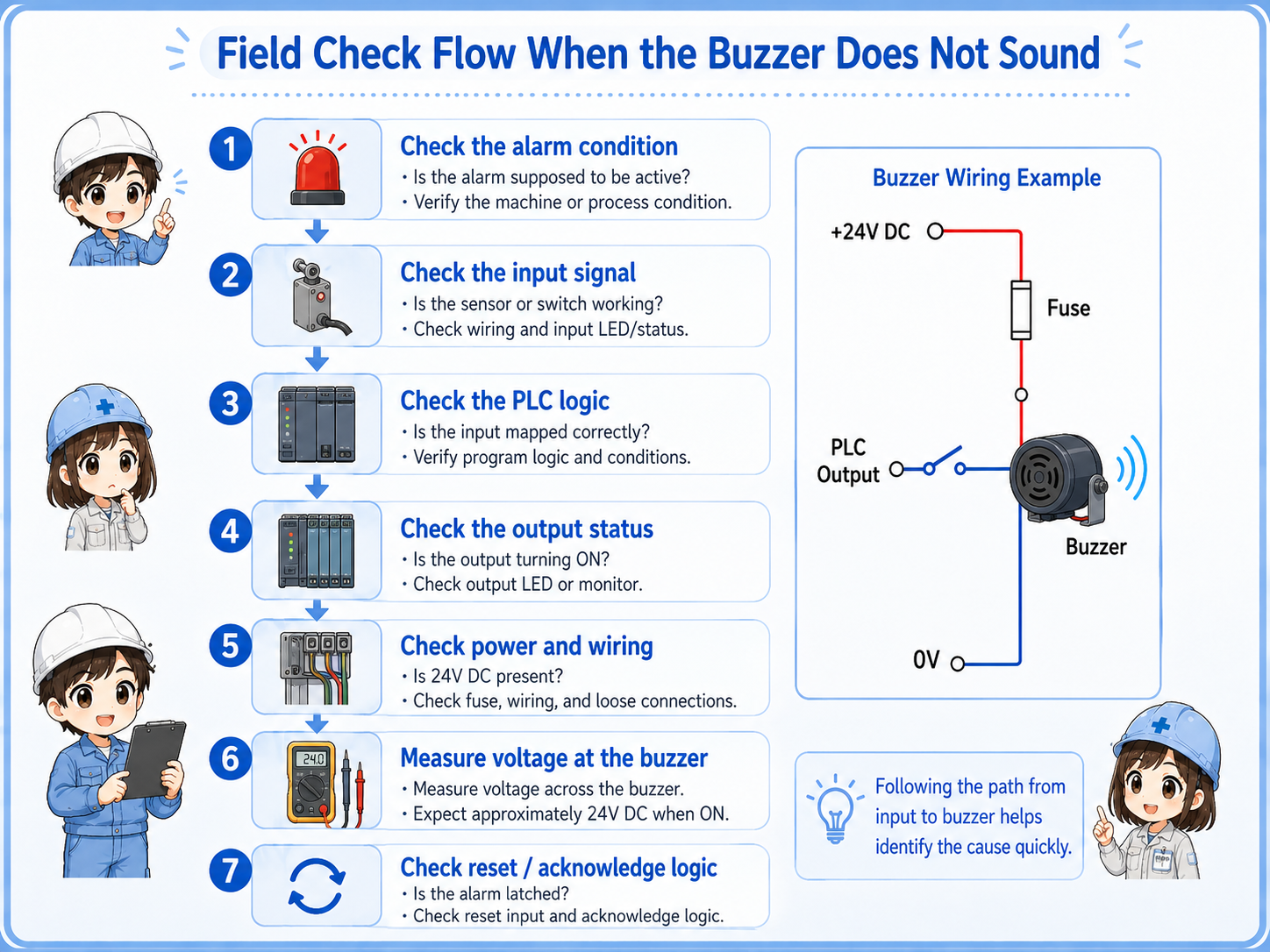

When a buzzer does not sound, do not check only the buzzer body. First confirm whether the alarm condition and PLC output are actually ON.

So I should follow the path: alarm input, logic, output, power supply, terminal wiring, and then the buzzer itself.
A buzzer circuit is simple when you separate alarm detection, output control, and reset behavior.
The abnormal condition that starts the buzzer logic.
The PLC output or relay contact that supplies power to the buzzer.
The logic that keeps the alarm active until it is acknowledged or reset.
The condition that clears the held alarm or silences the buzzer.
If you can read these four parts, you can understand most basic buzzer circuits. For real machines, always confirm the actual device voltage, output rating, wiring method, alarm priority, and official manuals before changing the circuit.