What are a contacts and b contacts?
In Japanese control practice, a contact and b contact are common names for normally open and normally closed contacts.
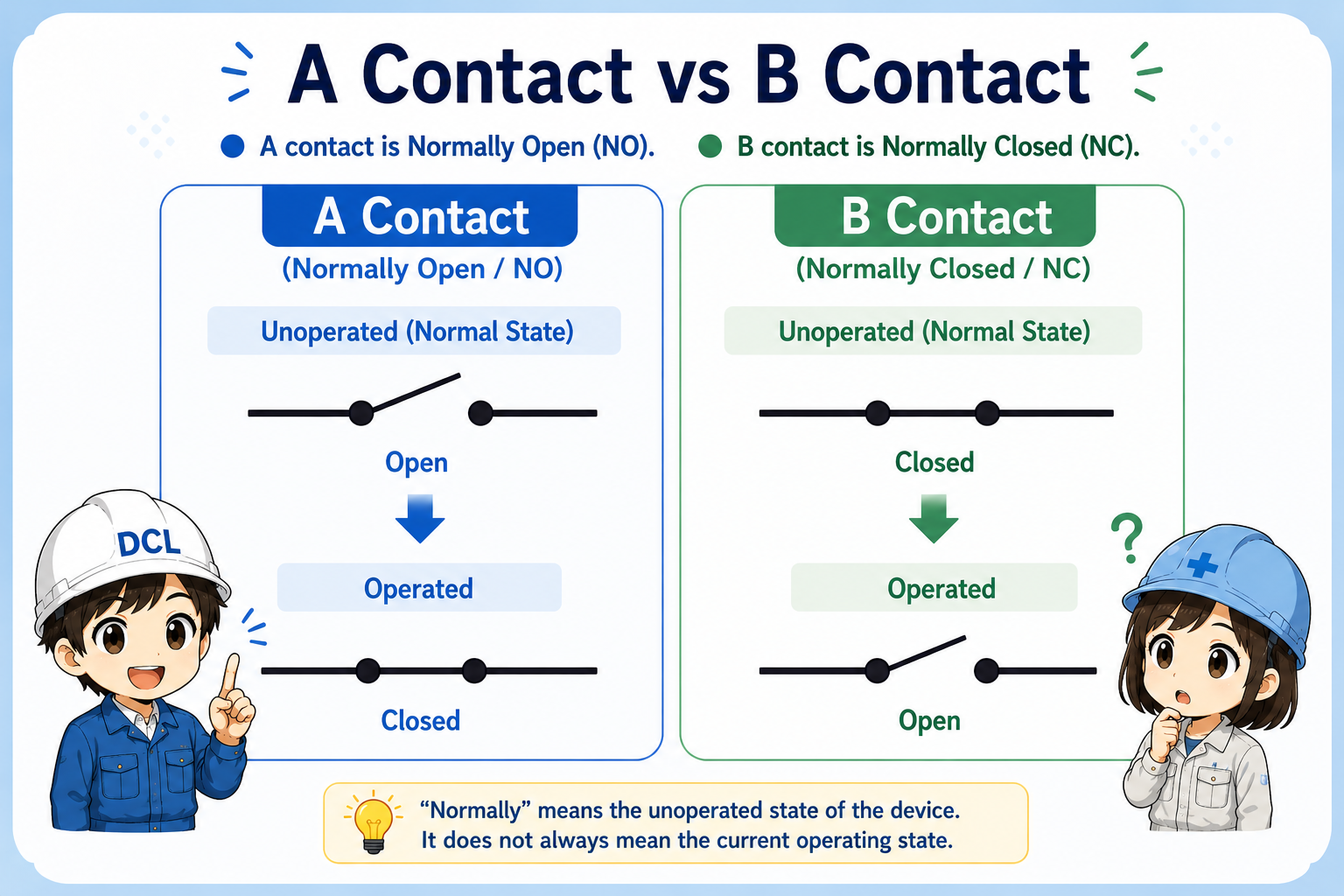
An a contact is a contact that is open in its normal state and closes when the device operates. In English, this is usually called a normally open contact, or NO.
A b contact is a contact that is closed in its normal state and opens when the device operates. In English, this is usually called a normally closed contact, or NC.
The most important point
“Normally” means the unoperated state of the device. It does not always mean the current state you see during machine operation.

When you read contacts, first ask: what is the normal, unoperated state?

So I should not judge only from whether the machine is moving right now?
Exactly. Normal state and current operating state are different ideas.
A contact = normally open, B contact = normally closed
The easiest way to remember the difference is to focus on whether the contact is open or closed before operation.
| Contact name | English name | Normal state | When operated |
|---|---|---|---|
| A contact | Normally open contact / NO | Open | Closes |
| B contact | Normally closed contact / NC | Closed | Opens |
Simple memory rule
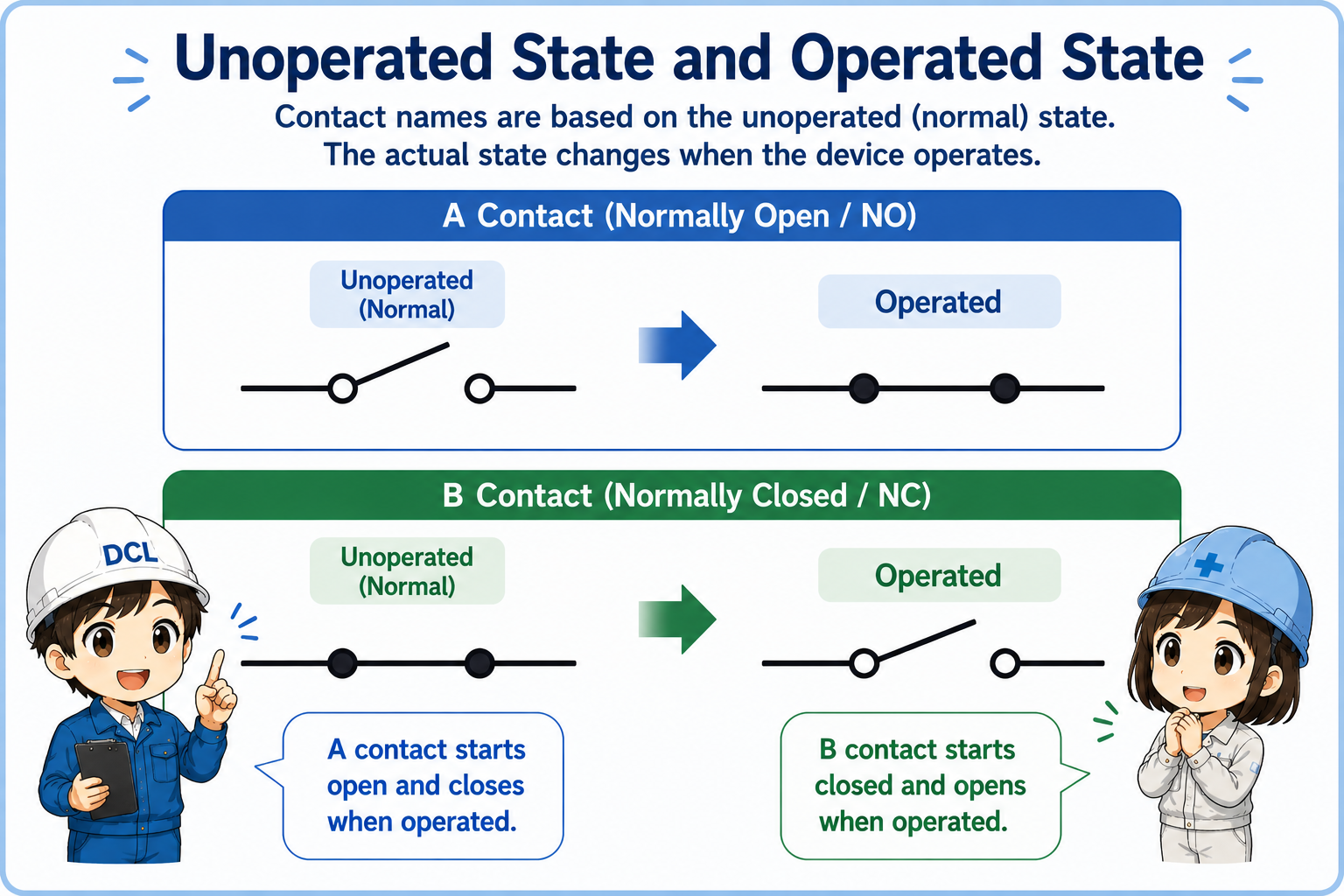
NO starts open and becomes closed. NC starts closed and becomes open.
Unoperated state and operated state
Many mistakes happen because people mix up normal state, operated state, and actual machine condition.
For a push button, the unoperated state is the condition before the button is pressed. For a relay, it is the condition before the coil is energized. For a limit switch, it is usually the condition before the actuator is pressed or moved.
1. Identify the device
Push button, relay, limit switch, sensor output, or contact block.
2. Check normal state
Open means NO. Closed means NC.
3. Imagine operation
NO closes. NC opens.
4. Read the circuit
Decide when current or signal can pass.
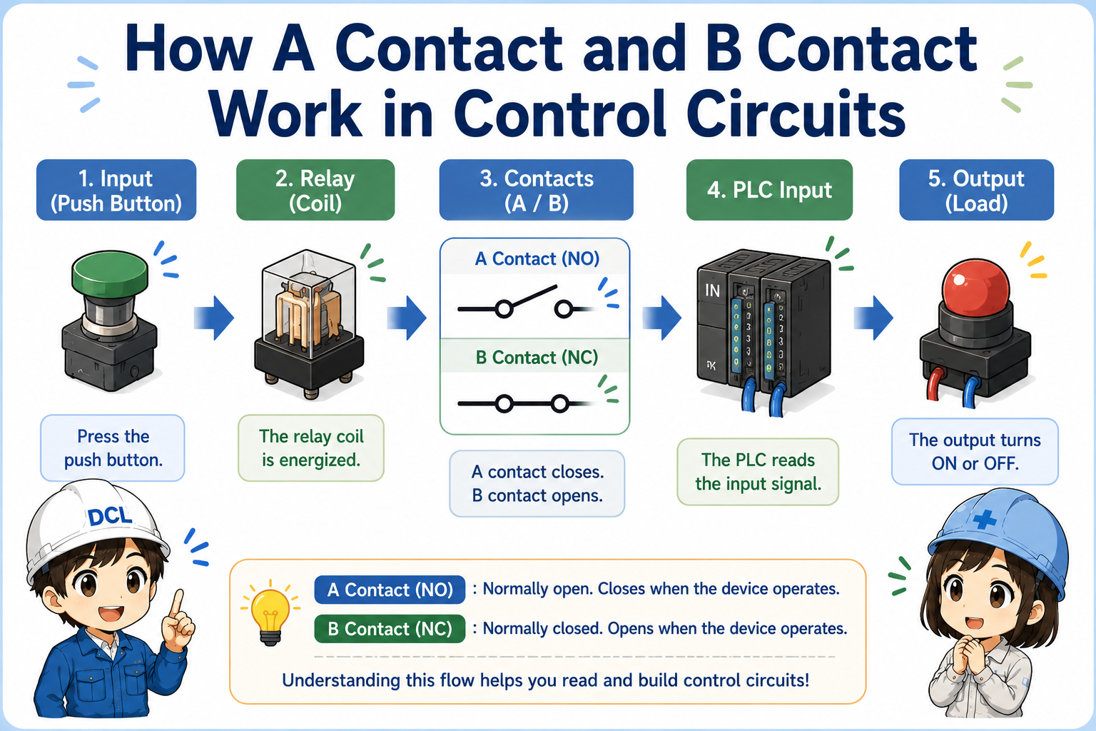
Where you see NO and NC contacts
The same idea appears in push buttons, relays, selector switches, limit switches, and PLC input circuits.
Push buttons
A start button is often NO. It closes only while pressed. A stop button is often NC. It opens when pressed.
Relays
Relay contacts change state when the relay coil is energized.
Limit switches
The contact state changes when the mechanical actuator is moved.
PLC inputs
The PLC sees input ON or OFF, but the field contact may be NO or NC depending on the wiring purpose.
Field-friendly view
Do not memorize only the part name. Trace what happens to the signal when the device is not operated and when it is operated.
How NO and NC appear in PLC input checks
A PLC input only shows whether voltage or signal is present. The field contact logic must be understood from the wiring and device state.
For example, an NC stop button may keep a PLC input ON during normal operation. When the button is pressed, the contact opens and the input turns OFF. This is normal behavior for that circuit, even though OFF may look like “nothing is happening” at first glance.
Important PLC reading habit
Input ON does not always mean the device is operated. Input OFF does not always mean the device is broken. Check the contact type and wiring purpose.
Field check points
When checking contacts in the field, confirm the normal state, operation state, terminal numbers, and PLC input status together.
Check the drawing
Confirm whether the circuit expects an NO contact or NC contact.
Check the device state
Know whether the button, relay, switch, or sensor is currently operated.
Check terminals
Terminal numbers or contact block markings can help identify NO and NC.
Check safely
Follow site rules before measuring voltage, continuity, or touching terminals.
Common mistakes when reading contacts
Most confusion comes from judging by the current machine state instead of the normal state.
| Mistake | Why it causes confusion | Better way to think |
|---|---|---|
| Thinking “normal” means machine running | Normal in NO/NC means unoperated state, not production running condition. | Ask whether the device itself is operated. |
| Judging only from PLC input ON/OFF | The same input status can have different meanings depending on wiring. | Check the field contact type and the circuit drawing. |
| Mixing up push button and relay behavior | A push button changes when pressed. A relay contact changes when its coil is energized. | Identify what action operates the contact. |
| Replacing parts before understanding logic | A contact may be working correctly even if the signal looks opposite at first. | Compare normal state, operated state, and actual measured signal. |
Do not bypass NC contacts casually
NC contacts are often used for stop, alarm, interlock, and safety-related logic. Do not bypass or change wiring without understanding the circuit and following site rules.