Good fit for
- Beginners learning PLC counter circuits.
- People who want to understand pulse counting and reset signals.
- Technicians checking why a counter does not count correctly.
A counter circuit counts input pulses and turns ON an output when the count reaches a set value. This guide explains the basic idea, simple ladder logic, reset timing, and field checks.
A counter circuit is a basic PLC circuit that counts repeated input signals.
In PLC control, a counter circuit is used when you need to count how many times something happened. For example, it can count parts passing a sensor, machine cycles, push-button operations, or repeated pulses from a limit switch.
The basic idea is simple: each valid input pulse increases the count. When the count reaches the preset value, the counter output condition becomes true.
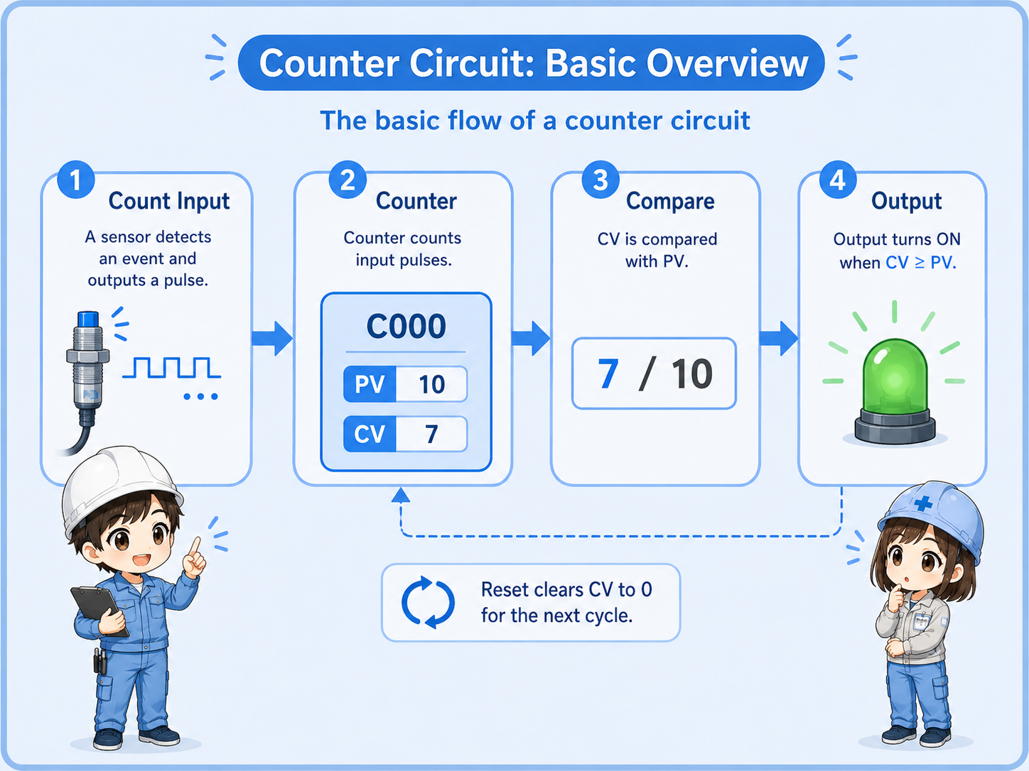
A counter is not just an ON/OFF contact. It stores a count value, so you need to understand both the count input and the reset condition.
A counter becomes easier to read when you separate each role.
| Term | Meaning | Field image |
|---|---|---|
| Count input | The condition or pulse that makes the counter add one count. | A sensor detects one product passing. |
| Preset value | The target count. The counter output turns ON when this value is reached. | Stop or signal after 10 products. |
| Current value | The count value currently stored in the counter. | The PLC currently remembers 7 counts. |
| Reset | The condition that clears the current count back to zero. | Clear the count after one batch is complete. |
Counter instruction names, data formats, and reset behavior differ by PLC manufacturer and model. Always check the official manual for the PLC you are using.
For beginners, focus on the relationship between input pulse, counter, output, and reset.
A simple up counter circuit usually has three important parts: the pulse condition that increments the counter, the contact that becomes true when the counter reaches the preset value, and the reset condition that clears the count.
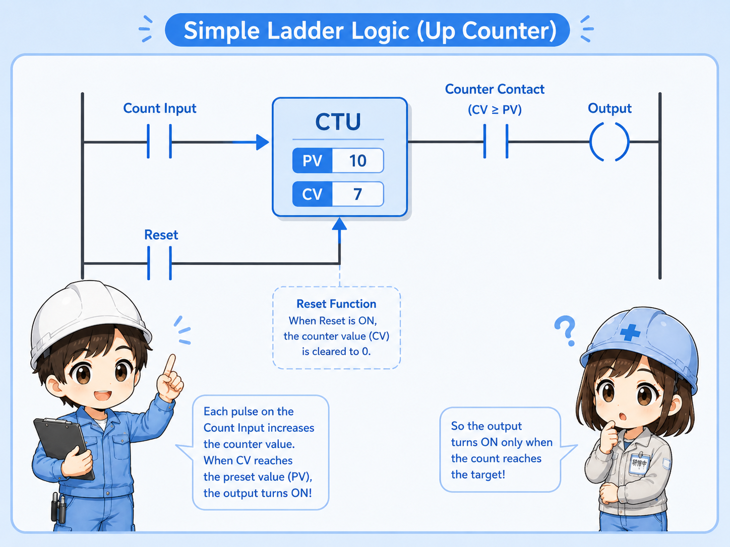
A sensor, button, or internal condition creates a count pulse.
The current count increases when a valid pulse is detected.
When the current count reaches the preset value, the counter contact turns ON.
The reset condition clears the count for the next operation.
A counter should normally count one pulse at a time. If the input stays ON, bounces, or repeats unexpectedly, the counter may count differently from what you expect. Edge detection or one-shot logic may be needed depending on the program.
Counter circuits are common in batch, cycle, and production counting applications.
Count products detected by a photoelectric sensor or proximity sensor.
Count how many times a cylinder, actuator, or machine cycle has operated.
Turn ON a signal when a required number of parts or operations is reached.
Use accumulated counts as a reference for inspection or replacement timing.
When a counter does not behave as expected, do not only check the counter instruction. Also check the input device, wiring, pulse width, sensor position, and reset timing.
Most counter problems come from misunderstanding the input or reset condition.
| Symptom | Likely point to check | Basic idea |
|---|---|---|
| Counter does not count | Input condition, sensor signal, wiring, PLC input monitor | Confirm that the PLC actually receives a clean count signal. |
| Counter counts too many times | Input bouncing, repeated pulses, unstable sensor detection | Check if one real event is creating multiple PLC pulses. |
| Output does not turn ON | Preset value, current value, counter contact, output condition | Confirm whether the current count has really reached the target. |
| Count disappears unexpectedly | Reset condition, power cycle behavior, program scan timing | Check whether another rung is resetting the counter. |
Start from the physical signal, then check the PLC program.
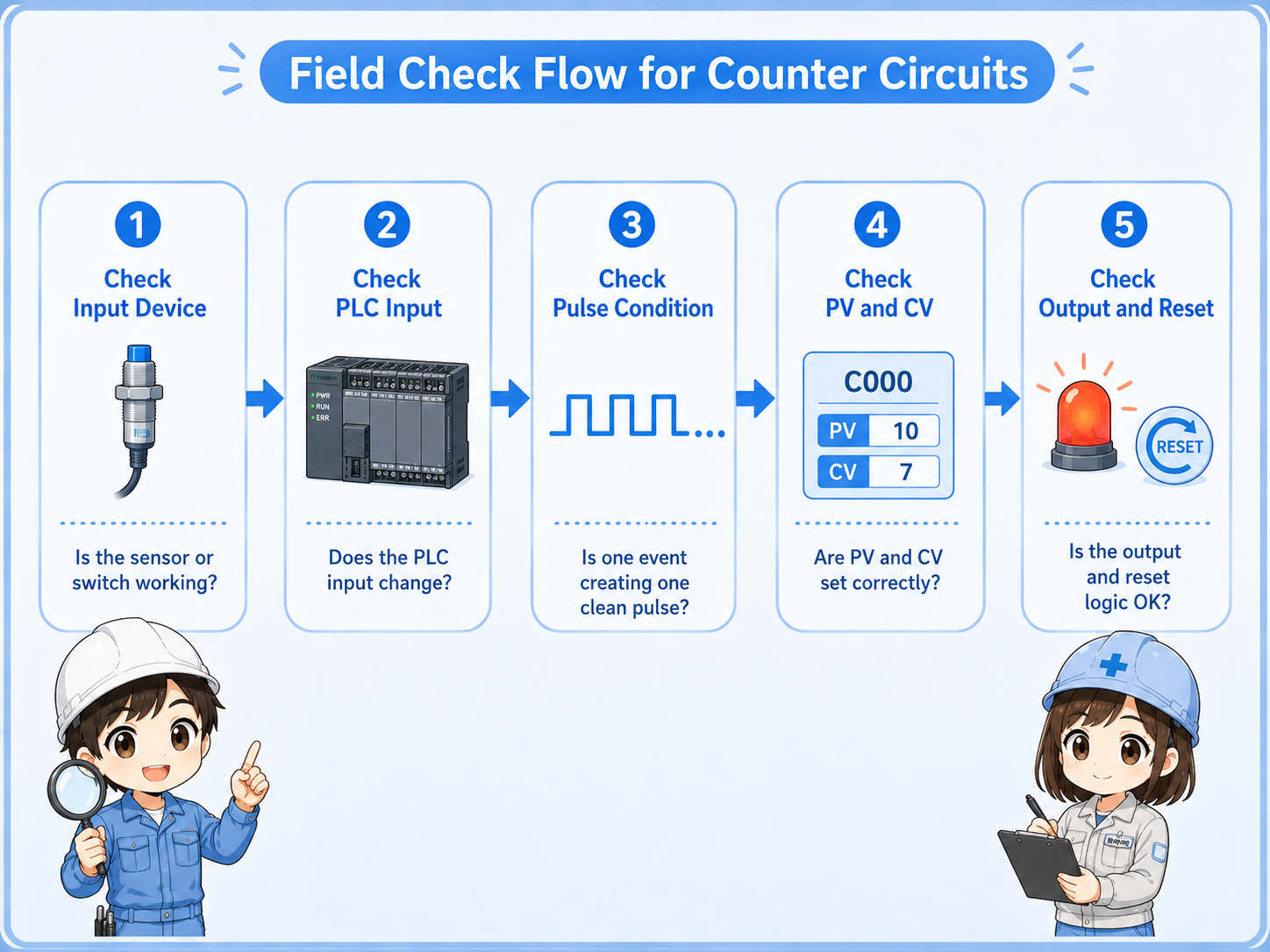

When a counter does not count, start with the real input. If the PLC input is not changing, the counter instruction cannot count anything.

So I should not look only at the counter value. I should also check the sensor, input monitor, pulse condition, and reset rung.
A counter circuit is simple when you separate counting, reaching the target, and resetting.
The pulse or condition that increases the count.
The target count that the counter compares against.
The condition that turns ON when the target count is reached.
The condition that clears the current count for the next operation.
If you can read these four parts, you can understand most basic PLC counter circuits. For real machines, always confirm the PLC model, instruction behavior, scan timing, and official manual before changing the program.