What are control panel wire colors?
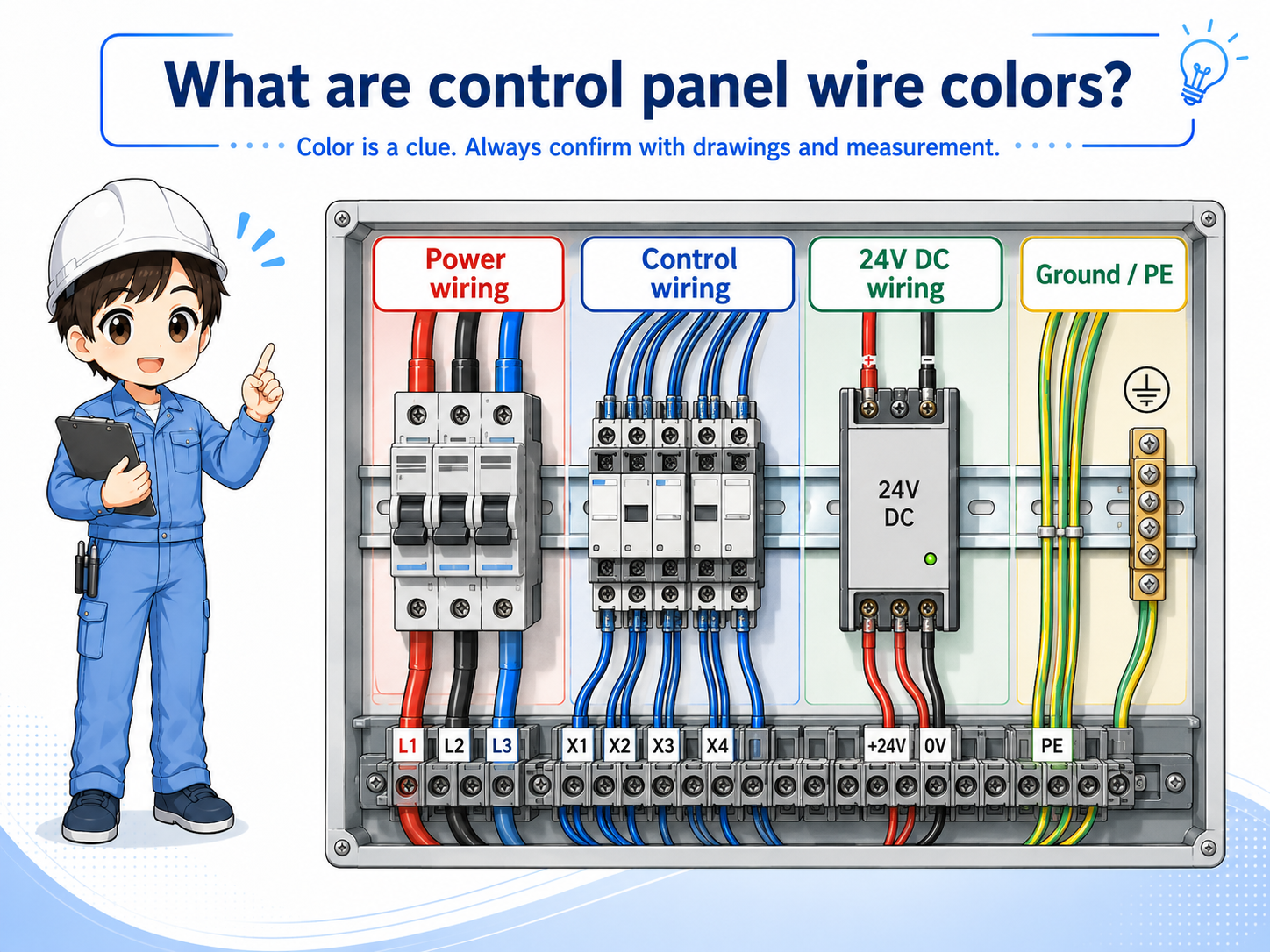
Wire colors are used to make wiring easier to identify, but they must be checked together with drawings and measurements.
In a control panel, many wires run close to each other. If all wires looked the same, tracing power, control signals, DC circuits, and ground wiring would be much harder.
Wire colors help workers quickly notice what kind of circuit a wire may belong to. However, color is only a guide. The correct meaning depends on the panel design, drawing, company rules, local standards, and actual wiring condition.
The simple way to think about it
A wire color is a clue. A wire number, terminal number, drawing, and voltage measurement are the evidence.
Why wire colors are used in control panels
Color separation helps prevent confusion during wiring, inspection, troubleshooting, and modification work.
Wire colors make a control panel easier to read at a glance. They can help separate power circuits, control circuits, DC circuits, and protective earth wiring.
This is especially useful during maintenance. When a machine stops, the technician can use color as an early clue before checking the drawing, terminal number, wire marker, and measured voltage.
Faster identification
Color helps you notice the possible circuit type before reading every wire number.
Cleaner panel work
Separated colors make wiring easier to organize and inspect inside the panel.
Maintenance support
During troubleshooting, color can help you choose where to look first.
Mistake prevention
Clear color separation can reduce wiring mistakes, but it does not replace verification.

Wire color helps you read the panel faster, but never decide only by color. Always confirm with the drawing and measurement.

So color is useful, but I should not treat it as proof by itself.
Typical wire color groups
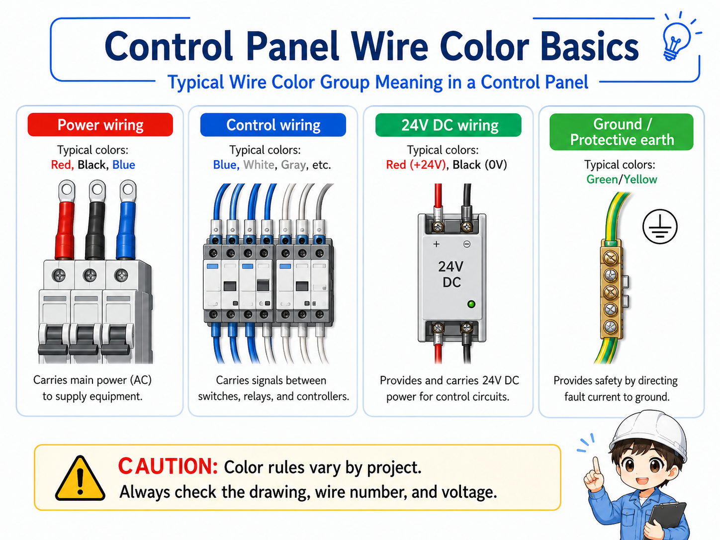
Exact color rules vary, but many panels separate power, control, DC, and ground wiring by color.
There is no single color explanation that applies to every control panel. Different countries, companies, machines, and panel builders may use different rules. Older panels may also differ from current standards.
Still, it is useful to understand the idea of color grouping. The table below shows a general way to think about the role of wire colors. Always check the actual drawing and project standard before deciding.
| Group | Typical purpose | What to check |
|---|---|---|
| Power wiring | Wires related to main power, motor power, or higher-energy circuits. | Voltage class, breaker, contactor, overload, and drawing symbol. |
| Control wiring | Wires used for relay circuits, control signals, lamps, switches, and interlocks. | Control voltage, relay contact, PLC input/output, and terminal number. |
| DC wiring | Wires related to 24V DC power, sensors, PLC I/O, and common lines. | 24V, 0V, common wiring, polarity, and signal type. |
| Ground / protective earth | Protective grounding and earth-related wiring. | Ground terminal, bonding, continuity, and applicable standard. |
Color rules are not universal
The same color may not mean the same thing in every panel. Treat color as a starting point, then confirm with drawings, labels, terminal numbers, and measurement.
How wire color connects with drawings and wire numbers
The best way to read wiring is to combine wire color, wire number, terminal number, and the electrical drawing.
Wire color gives a quick visual clue, while the wire number and terminal number help identify the exact connection. The drawing explains what the circuit is supposed to do.
For example, a wire may look like a 24V control wire based on color, but the real confirmation comes from the wire number, terminal destination, PLC I/O point, and measured voltage.
1. Color
Use color as a quick clue for the possible circuit group.
2. Wire number
Use the marker tube to identify the exact wire.
3. Terminal
Check the terminal block number and destination.
4. Drawing / voltage
Confirm the circuit role and actual electrical state.
Good field habit
When color, wire number, terminal number, drawing, and measured voltage all agree, your judgment becomes much more reliable.
Field checks for control panel wire colors
When checking a panel, do not stop at color. Confirm what the wire actually is and where it goes.
Wire color mistakes can happen during panel modification, repair, temporary wiring, or old equipment work. A wire can also be replaced with a different color if the correct material was not available.
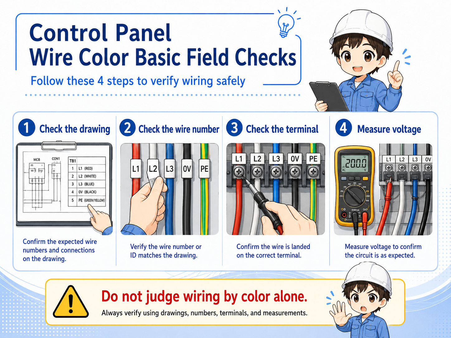
1. Check the drawing
Confirm what the circuit should be before judging the wire by appearance.
2. Check the wire number
Use the marker tube to identify the exact wire and compare it with the drawing.
3. Check the terminal
Confirm that the wire is connected to the correct terminal block or PLC I/O point.
4. Measure voltage
Do not assume voltage from color. Measure and confirm the actual electrical state safely.
Do not judge live wiring by color alone
A wrong assumption about wire color can lead to electric shock, short circuit, equipment damage, or incorrect troubleshooting. Use proper measuring tools and follow the site's safety procedure.
Common mistakes to avoid
Most mistakes happen when color is treated as the final answer instead of the first clue.
- Assuming the same color rule applies to every machine and every company.
- Ignoring old modifications that may not follow the current drawing.
- Trusting color even when the wire number or terminal number does not match.
- Measuring the wrong point because two wires have similar colors.
- Replacing a wire without updating the marker, drawing, or project record.
- Thinking ground, common, and 0V are always the same just because they look similar.
Simple field mindset
Color helps you start tracing. Wire number, terminal number, drawing, and measurement help you finish tracing correctly.