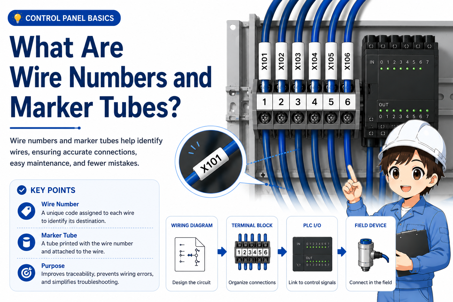
What are wire numbers and marker tubes?
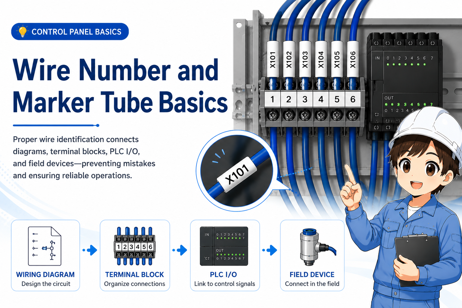
Wire numbers identify wires so you can trace them between drawings, terminal blocks, PLC I/O, and field devices.
A wire number is an identification mark attached to a wire. In many control panels, the number is printed on a small marker tube and placed near the end of the wire. This helps workers identify where the wire belongs and what it connects to.
Without wire numbers, tracing a panel can become a guessing game. With clear wire numbers, you can compare the actual wire with the drawing, terminal number, PLC I/O address, and field device connection.
The simple way to think about it
A wire marker is like a name tag for a wire. It does not make the circuit work by itself, but it helps people read, check, and repair the circuit correctly.
Why wire numbers are important in control panels
Wire numbers reduce confusion when many similar wires are connected in a small space.
Control panels often contain many wires with similar colors and routes. If a worker only looks at wire color or physical location, it is easy to follow the wrong wire. Wire numbers give a more reliable way to connect the real panel to the drawing.
Tracing
Wire numbers help you follow one signal from a drawing to a terminal and then to a device.
Troubleshooting
When a signal does not arrive, the wire number helps narrow down where to check.
Maintenance
Clear markers help the next worker understand the wiring without relying only on memory.
Modification work
When changing wiring, matching the marker and drawing helps prevent connection mistakes.

When many wires look the same, the wire number is what lets you trace the circuit calmly. Do not rely only on wire color or position.

So the marker is not just for neatness. It is important for troubleshooting and future maintenance too.
How wire numbers connect drawings, terminal blocks, PLC I/O, and field devices
A wire number should help you move between the drawing and the actual panel without losing the signal path.
In a control system, one signal may appear in several places: the electrical drawing, a terminal block, a PLC input or output unit, and a field device such as a sensor, push button, lamp, or solenoid valve.
Wire numbers help connect these places together. When the drawing and marker tubes are consistent, you can trace the signal step by step instead of guessing from the physical wiring route alone.
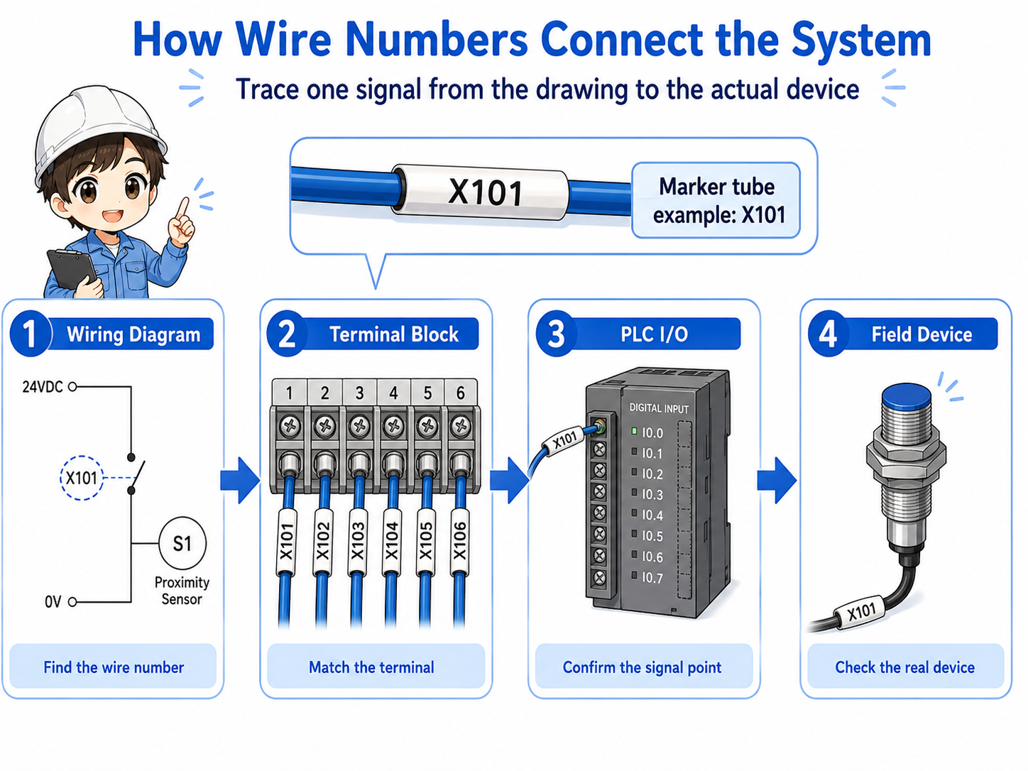
1. Drawing
Find the wire number, terminal number, and device name on the drawing.
2. Terminal block
Check which terminal the marked wire is connected to.
3. PLC I/O
Confirm whether the wire connects to an input or output point.
4. Field device
Trace the signal to the sensor, switch, lamp, relay, or valve.
Different workplaces use different rules
Some panels use wire numbers based on drawing line numbers, while others use terminal numbers, device numbers, or company-specific rules. Always follow the project drawing and local standard.
How to trace wiring using wire numbers
Start from one known point and compare the marker, drawing, terminal, and measured signal.
When you need to trace a wire, do not start by pulling wires or moving them around. First, choose one known point: a terminal number, PLC I/O address, device name, or wire number from the drawing.
Then follow the information one step at a time. If the drawing says wire number “X123” goes from a terminal block to a PLC input, look for the same marker on the actual wire and confirm that the connection matches.
| Check point | What to compare | Why it matters |
|---|---|---|
| Drawing | Wire number, terminal number, device name, and PLC address. | The drawing tells you the intended connection. |
| Actual marker | The printed number on the marker tube attached to the wire. | The marker helps identify the real wire in the panel. |
| Terminal | The terminal block position and terminal number. | The terminal confirms where the wire is physically connected. |
| Signal | Voltage, continuity, input monitor, or output state. | The measurement confirms what is actually happening electrically. |
Good field habit
When the marker, drawing, terminal number, and measured signal all agree, your tracing becomes much more reliable.
Field checks for wire numbers and marker tubes
Check whether the marker is present, readable, correct, and consistent with the drawing.
Wire markers are small, but problems with them can slow down troubleshooting. A missing marker, wrong marker, rotated marker, or unreadable marker can cause a worker to follow the wrong wire.
1. Missing marker
If the marker tube is missing, the wire may be hard to identify later even if the circuit works now.
2. Wrong marker
If the marker does not match the drawing or terminal, someone may trace the wrong signal.
3. Unreadable marker
If the text is faded, dirty, hidden, or rotated, future maintenance becomes harder.
4. Drawing mismatch
If the actual wiring was changed but the drawing was not updated, the marker alone may not be enough.
Do not trust one clue only
A marker tube can be wrong. A drawing can be old. A terminal may have been changed. Always compare multiple clues before disconnecting or changing a wire.
Common mistakes to avoid
Most mistakes happen when someone assumes the marker is correct without checking the rest of the circuit.
- Following only the physical wire route and ignoring the drawing.
- Trusting a marker even when the terminal number does not match.
- Removing a wire before recording its marker and terminal position.
- Changing a wire without updating the drawing or marker tube.
- Leaving duplicate or unclear wire numbers after modification work.
- Not checking the PLC input monitor or voltage after tracing the wire.
Simple field mindset
A wire number is useful because it connects information. Use it together with the drawing, terminal number, device name, and actual electrical signal.