What is a PLC I/O unit?
A PLC I/O unit is the part of a PLC system that connects the controller to real-world devices.
A PLC does not control a machine by itself. It needs to receive signals from the field and send signals back to the machine. The parts that handle these signals are called I/O units or I/O modules.
I/O means Input / Output. Inputs are signals going into the PLC. Outputs are signals going out from the PLC. This simple direction is one of the most important ideas when reading a control panel.
The basic idea
Input units listen to the machine. Output units command the machine. If you remember this, PLC wiring becomes much easier to follow.

When you look at a PLC panel, first separate input wiring and output wiring. That alone makes the drawing much easier to read.

So sensors and switches usually go to inputs, and lamps or relays are usually driven from outputs?
Exactly. That is the first big split to understand.
Input unit vs output unit
Input units receive information. Output units operate devices.
| Item | Input unit | Output unit |
|---|---|---|
| Signal direction | Field device → PLC | PLC → field device |
| Typical devices | Push button, limit switch, proximity sensor, photoelectric sensor, pressure switch | Indicator lamp, relay coil, solenoid valve, buzzer, signal tower |
| What the PLC sees or does | The PLC reads ON/OFF information from the field. | The PLC turns an external load ON or OFF. |
| Common check point | Check 24V supply, COM wiring, sensor output, and input LED. | Check output LED, output terminal voltage, load wiring, and load power. |
Input unit
An input unit tells the PLC whether a field condition is ON or OFF.
Output unit
An output unit lets the PLC operate a device outside the PLC.
Signal flow: field device → PLC → output device
A simple machine signal often flows from a sensor into the PLC, then from the PLC to an output device.
For example, a push button may send a signal to a PLC input. The PLC program checks that input, then turns on an output. That output may operate a relay, lamp, or solenoid valve.
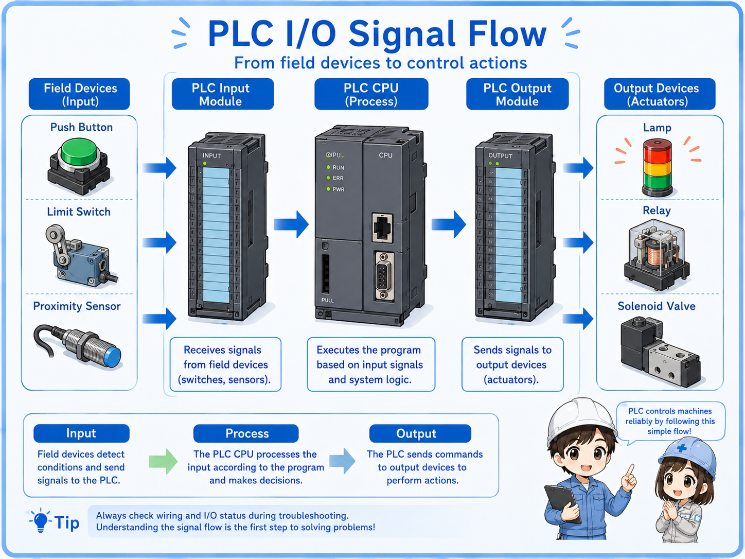
1. Field input
A switch or sensor changes state in the machine.
2. Input unit
The PLC input unit receives the signal.
3. PLC program
The PLC logic decides what should happen.
4. Output unit
The PLC output unit turns ON or OFF.
5. Load device
A lamp, relay, valve, or buzzer operates.
Field-friendly view
When troubleshooting, check the flow in order: field device, input LED, PLC monitor, output LED, output terminal, and load device.
Terminal numbers and common terminals
Terminal numbers show where each signal connects. Common terminals provide the shared side of the circuit.
PLC I/O modules usually have terminal numbers such as X0, X1, X2 for inputs or Y0, Y1, Y2 for outputs. The naming depends on the PLC series, but the purpose is the same: each terminal corresponds to a signal point.
The COM or common terminal is also important. It is the shared reference or supply side for a group of inputs or outputs. If COM wiring is missing or wrong, several points may not work at the same time.
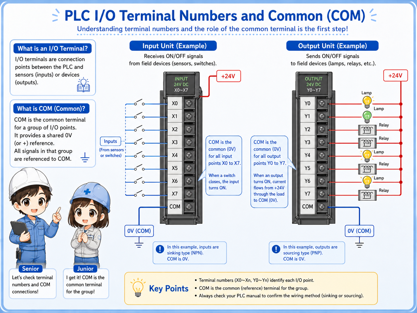
Terminal number
Connects the wiring point to a PLC address or I/O point.
COM terminal
Acts as the shared side for a group of I/O circuits.
+24V and 0V
Many input circuits and sensor circuits depend on correct 24V DC wiring.
Group wiring
One COM problem can affect several input or output points in the same group.
Important beginner point
Do not check only the signal terminal. Check the common side too. A missing COM can make a good device look faulty.
How field devices connect to PLC I/O units
Inputs and outputs connect to different kinds of field devices, so the wiring direction is different.
Input wiring usually connects devices that report a condition to the PLC. Output wiring connects devices that the PLC operates. This is why reading the device type helps you understand the I/O point.
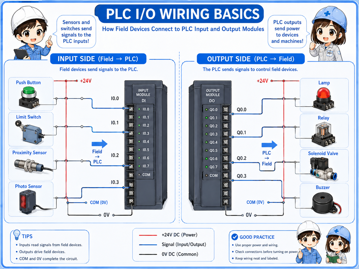
| Device | Usually connected to | Reason |
|---|---|---|
| Push button | Input unit | The PLC reads whether the button is pressed. |
| Sensor | Input unit | The PLC reads whether the sensor is ON or OFF. |
| Indicator lamp | Output unit | The PLC turns the lamp ON or OFF. |
| Relay coil | Output unit | The PLC drives the relay coil through an output point. |
| Solenoid valve | Output unit | The PLC energizes the valve coil to operate air or fluid movement. |
Simple way to remember
If the device tells the PLC something, it is probably an input. If the PLC tells the device to move, light, or operate, it is probably an output.
What to check in the field
When an input or output does not work, check the wiring path instead of guessing the failed part.
Input side checks
Check sensor power, switch contact, 24V signal, COM wiring, input terminal, and input LED.
Output side checks
Check PLC output LED, output terminal voltage, load power, load wiring, and the device itself.
Terminal checks
Check terminal numbers, loose screws, wrong wire numbers, and jumpers or common wiring.
Program monitor
Use PLC monitor status to compare field signal, input bit, output bit, and actual output device.
Do not short I/O terminals with meter probes
I/O terminals are often close together. When measuring voltage, use suitable probes and work carefully so you do not bridge adjacent terminals.
Safety notes before checking I/O wiring
PLC I/O circuits may use 24V DC, but the control panel can still contain dangerous power circuits.
Always follow the site rules and check the actual drawing. Do not assume all wiring near a PLC is low voltage. Nearby terminals may include AC power, motor circuits, or other hazardous circuits.
Before changing wiring, replacing a module, or removing terminal connectors, confirm whether power isolation, lockout, or machine stop procedures are required.
Use the drawing and terminal numbers together
The best check is not only looking at the PLC module. Compare the drawing, terminal number, wire number, and actual device location.