1. Start with the whole signal path
A limit switch problem can be mechanical, electrical, or program-side observation.
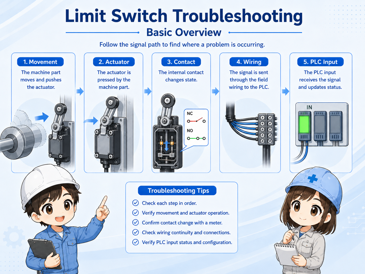
A limit switch changes contact state when a lever, roller, plunger, or actuator is moved by the machine. If the signal does not appear, the first step is to avoid assuming the switch is broken. The machine part may not be reaching the switch, the contact type may be misunderstood, or the PLC input may not be receiving the voltage.
A practical way to troubleshoot is to follow the signal path in order: mechanical movement → switch actuation → contact state → wiring → terminal block → PLC input.

When a limit switch does not respond, do not jump straight to replacement. First confirm whether the machine is actually pushing it correctly.

So the first check is physical movement, not only whether the PLC input is ON.
2. Check mechanical position and actuation amount
A small position shift can prevent the switch from changing state.
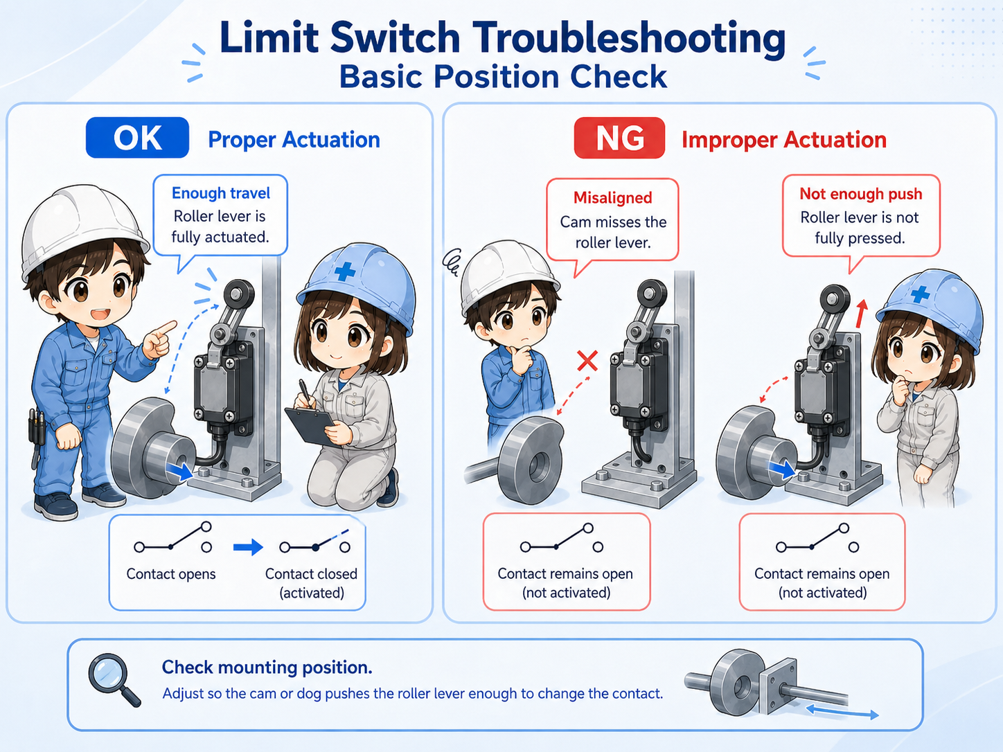
Many limit switch issues are caused by position rather than wiring. The dog, cam, workpiece, cylinder, stopper, or moving part may not reach the actuator far enough. Sometimes it touches the roller but does not push it to the operating point.
Also check the opposite condition. A switch may remain pressed and fail to release, especially if the lever is bent, the mounting position moved, or a mechanical stopper changed.
Actuation amount
Confirm whether the actuator is pushed far enough to change the contact state.
Mounting position
Check loose bolts, bracket movement, bent levers, and shifted dogs or cams.
Return movement
Confirm that the switch returns fully when the machine moves away.
Mechanical interference
Look for covers, cables, chips, oil, or parts blocking movement.
3. Confirm contact type and wiring
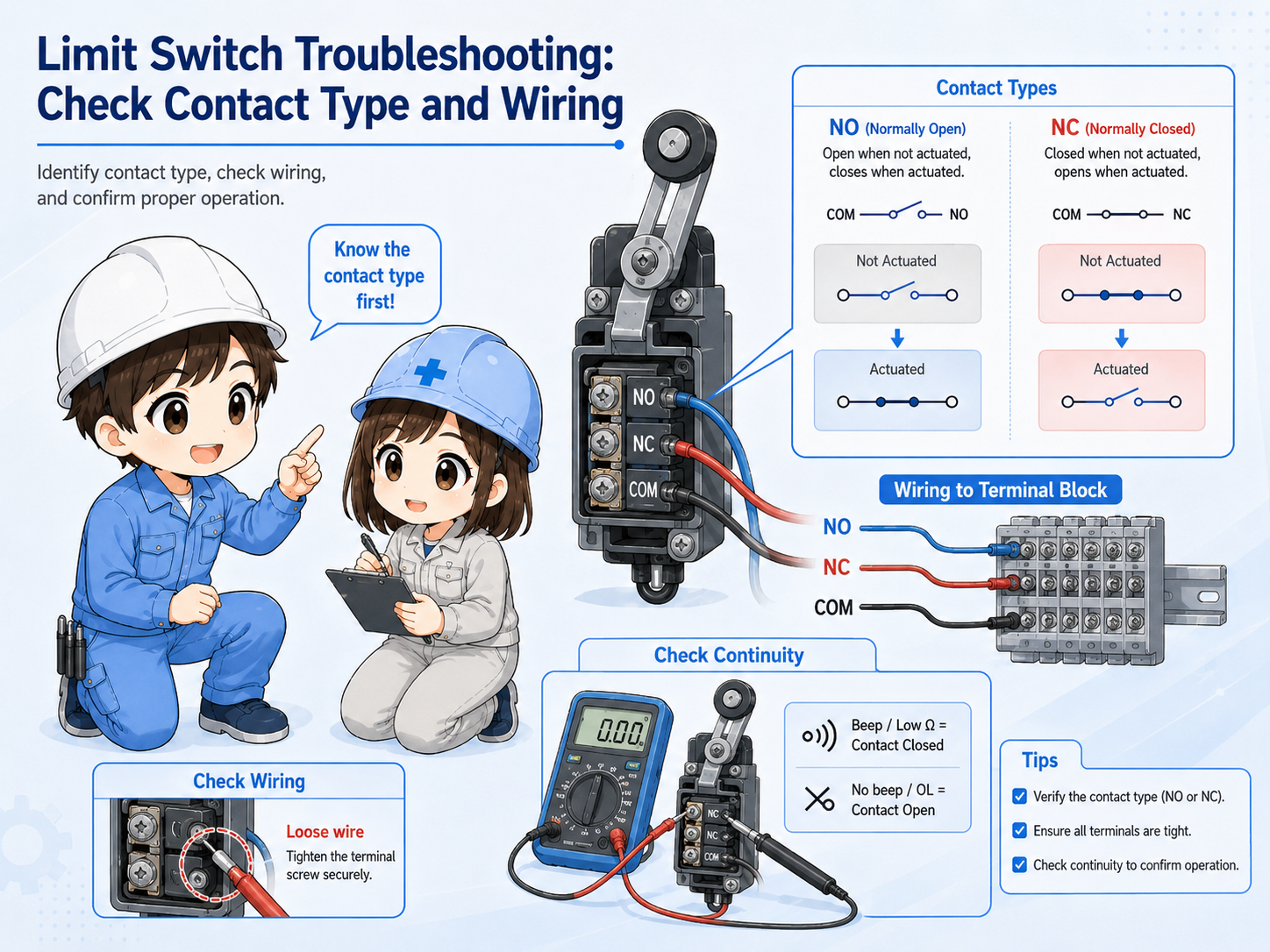
NO and NC contacts behave differently, so the expected ON/OFF state must be clear.
A limit switch may have NO, NC, or both contact terminals depending on the model. If the wrong contact is used, the signal may appear reversed. If the wiring is loose or the terminal is oxidized, the signal may be unstable or missing.
Before changing wiring, confirm the actual drawing, terminal labels, and device manual. In many field checks, it is useful to compare the expected contact state with the real continuity or voltage measurement.
| Check point | What to confirm | Common symptom |
|---|---|---|
| NO / NC contact | Whether the contact should close or open when actuated. | The input appears reversed or never matches the expected condition. |
| Terminal and wiring | Loose screws, broken wires, connector damage, and wrong terminal use. | The signal is intermittent or disappears during vibration. |
| Voltage or continuity | Measure according to the circuit type and site procedure. | The switch changes mechanically but the signal does not reach the next point. |
Use the drawing and manual
Terminal numbers and contact behavior vary by model. Always check the machine drawing and the official limit switch documentation before rewiring or replacing parts.
4. Check the PLC input after checking the field side
The PLC input is the end of the path, not the first cause by itself.
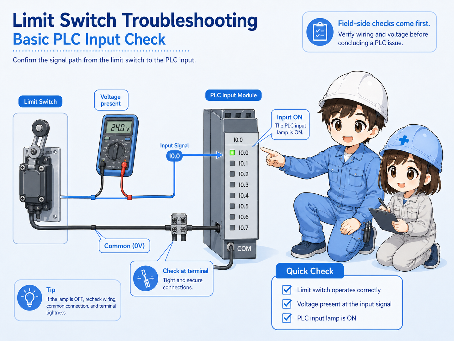
After checking the switch and wiring, confirm whether the PLC input indicator or monitor changes. If voltage reaches the input terminal but the PLC does not show the change, the input module, common wiring, address, or program condition may need to be checked.
However, if no voltage reaches the input terminal, the problem is still on the field side or wiring path. Separating these two conditions helps prevent unnecessary program changes.
1. Switch changes
The actuator movement changes the contact state.
2. Voltage reaches terminal
The signal arrives at the terminal block or PLC input point.
3. PLC input changes
The input lamp or monitor changes at the expected address.
5. Common mistakes when checking limit switches
Most confusion comes from checking only one side of the problem.
It is common to replace a switch before confirming the actuator travel, or to change a program before measuring the input voltage. A calm order of checks reduces unnecessary work and avoids creating new faults.
Do not force or bypass signals
For a normal position limit switch, forced signals can hide the real cause. For any safety-related use, bypassing or shorting signals can be dangerous. Follow site rules and official procedures.
- Do not assume the switch is broken just because the PLC input is OFF.
- Do not assume the PLC program is wrong before checking field voltage.
- Do not confuse NO and NC contact behavior.
- Do not ignore loose brackets, bent levers, or insufficient actuator travel.
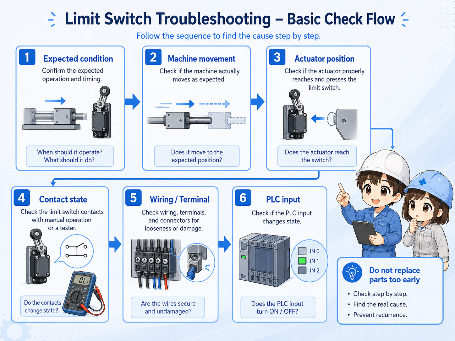
6. Field troubleshooting flow
Use a consistent order: movement, switch, wiring, terminal, PLC input.
When the machine is stopped and the limit switch signal is missing, write down what condition should make the input turn ON or OFF. Then check each point in the signal path. This makes it easier to explain the fault and avoid guessing.
1. Real machine position
Is the machine part actually reaching the switch position?
2. Actuator movement
Is the roller, lever, or plunger moving enough and returning fully?
3. Contact and wiring
Does the contact state or voltage change at the switch terminals?
4. PLC input point
Does the expected PLC input indicator or monitor change?
7. Quick summary
Limit switch troubleshooting is easiest when you follow the signal path in order.
If a limit switch does not respond, start with the real machine movement. Then check the actuator position, contact state, wiring, terminal block, and PLC input. This order helps avoid unnecessary replacement and makes the problem easier to explain.
Remember this
Do not start only from the PLC screen. A missing input may be caused by a mechanical position shift, insufficient switch travel, contact selection, broken wiring, or common wiring issue.
Related articles
These English articles are useful next steps after this troubleshooting guide.