Good fit for
- Beginners who see load cells on tanks, hoppers, presses, or weighing machines
- Electricians learning why a load cell needs an indicator or converter
- People checking unstable weight values, zero drift, or PLC analog inputs
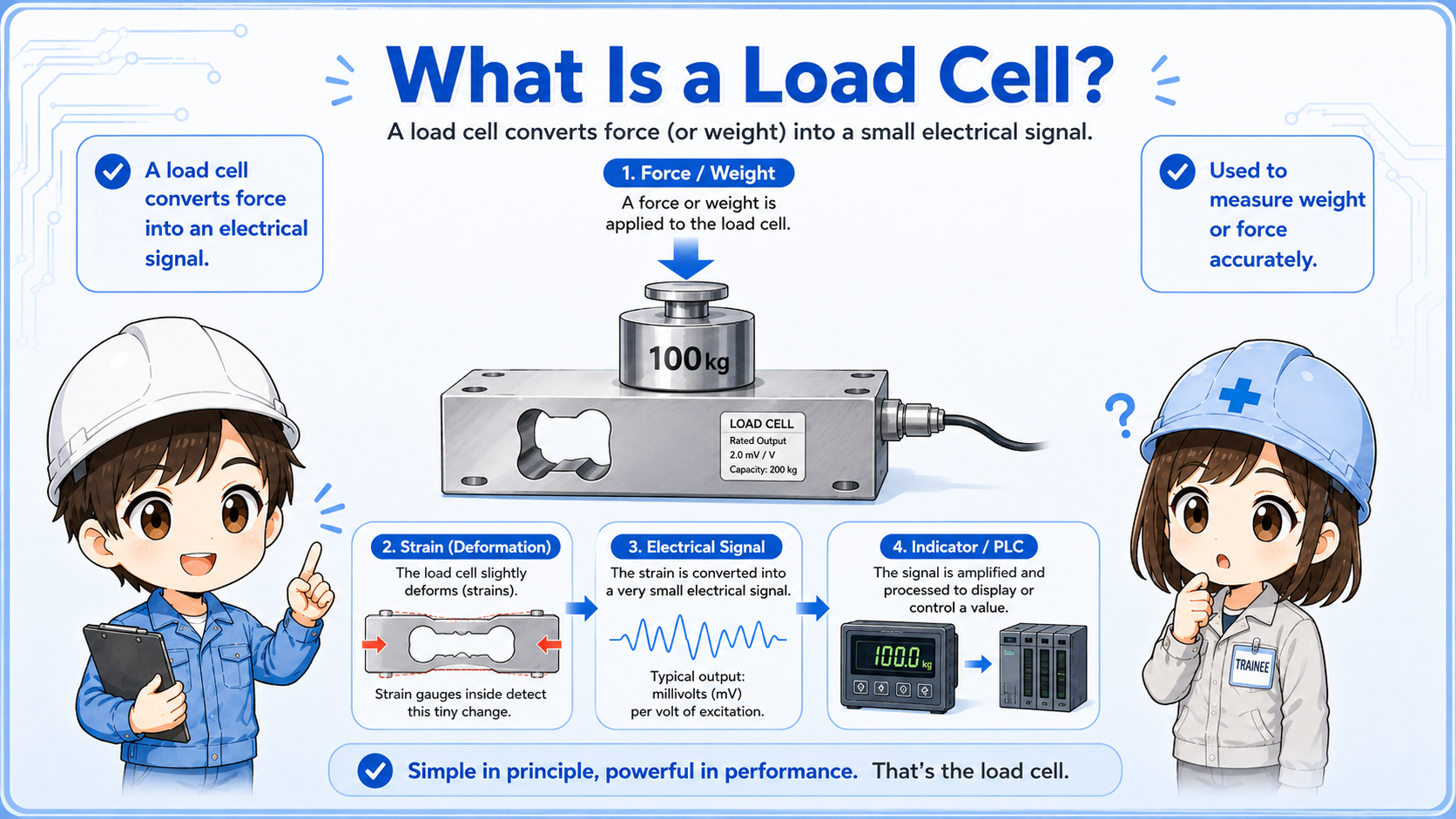
A load cell converts force or weight into an electrical signal. This guide explains where load cells are used, how they connect to indicators or transmitters, how PLCs read the signal, and what to check in the field.
A load cell is a sensor that converts force, weight, or load into an electrical signal.
A load cell is used when a machine needs to measure weight, pressing force, tension, or applied load. In many industrial systems, the load cell output is very small, so it is usually connected to an indicator, amplifier, or transmitter before the PLC reads it.
From a beginner viewpoint, it helps to think of a load cell as the part that feels the force. The indicator or transmitter is the part that turns that tiny signal into a value that can be displayed or used by a PLC.
Do not check only the PLC value. A load cell system includes the sensor, cable, indicator or transmitter, mounting condition, and mechanical load path.
Load cells are used anywhere a machine needs to measure weight, force, pressure through load, or material amount.
Common examples include tank weighing, hopper weighing, press force confirmation, filling machines, checkweighers, and tension measurement. The exact installation shape depends on the load direction and machine structure.
Measures the amount of material inside a tank or vessel.
Checks material weight during filling, batching, or discharge.
Confirms pressing, pushing, clamping, or tension force.

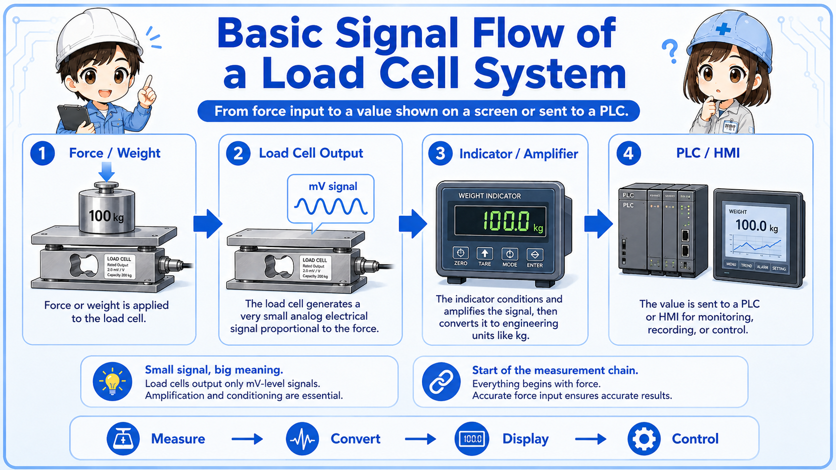
A load cell output is usually not treated like a simple ON/OFF sensor.
Many load cells output a very small analog signal. The indicator or transmitter supplies excitation voltage, reads the load cell signal, scales it, and outputs a display value, relay output, or analog signal such as 4–20 mA or 0–10 V for a PLC.
| Part | Role | Field viewpoint |
|---|---|---|
| Load cell | Converts force or weight into a small electrical signal | Check mounting, cable, damage, and load direction |
| Indicator / transmitter | Excites the load cell, amplifies the signal, and scales the value | Check zero, span, calibration, alarm, and output setting |
| PLC / control system | Reads analog value, relay output, or communication data | Check analog input range, scaling, wiring, and program use |
Unstable weight values can come from mechanical interference, vibration, poor mounting, side load, cable noise, or calibration issues—not only from PLC wiring.
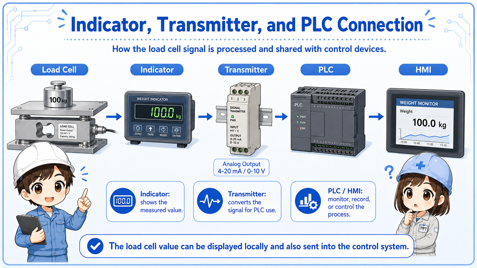
The PLC usually receives a processed value, not the raw load cell signal directly.
In many systems, the load cell connects to a weighing indicator or transmitter. That device displays weight, handles zero and span settings, and sends a signal to the PLC. The PLC may use the value for filling, batching, overload detection, or process control.
When troubleshooting, it is useful to compare the indicator display with the PLC value. If the indicator value is stable but the PLC value is wrong, the analog output, input range, scaling, or wiring may be the issue. If both are unstable, check the load cell, mounting, noise, and mechanical condition.
If a machine suddenly shows an incorrect weight, ask: did the mechanical load path change, was a cable touched, was zero adjusted, or did the PLC scaling change?
A short conversation helps separate sensor, wiring, scaling, and mechanical causes.

If the load cell value is unstable, do not start by changing PLC scaling. First compare the indicator display, check the cable, and look for vibration or mechanical interference.

So a strange weight value might be caused by the machine structure, not only by wiring?
Exactly. Load cell systems are mechanical and electrical together. Check the whole path from force to signal.
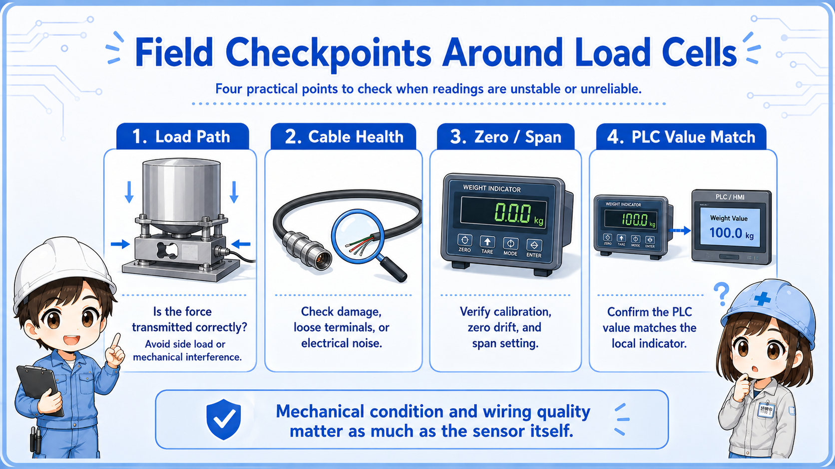
Most practical checks are about mounting, cable condition, zero value, calibration, noise, and PLC scaling.
Check side load, contact with surrounding parts, vibration, bolts, stopper contact, and uneven support.
Check shield grounding, connector condition, cable damage, noise sources, and terminal looseness.
Check zero drift, calibration state, indicator setting, tare value, and whether the value returns to zero.
Compare indicator display with PLC analog value, input range, scaling, and program calculation.
Calibration and adjustment procedures depend on the indicator and site requirements. Follow the machine manual, manufacturer manual, and quality procedure before changing settings.