1. Basic idea: a guard door condition becomes a safety input
A safety door switch checks whether a guard door is in the correct closed condition.
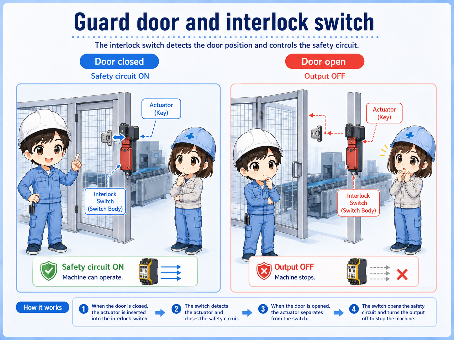
A safety door switch is installed on a guard door, safety fence, or access cover. When the door is closed correctly, the switch condition is valid. When the door opens, the safety input changes and the machine should move toward a safe stop condition according to the designed safety circuit.
The important point is that the switch is not only reporting door position to a PLC. It is part of a safety-related input path, usually connected to a safety relay or safety controller.

Do not treat this like a normal door sensor. A safety door switch is part of the safety condition that allows operation.

So if the door input is not valid, the machine may stay stopped even if the normal PLC program looks ready.
2. What “interlock” means in this context
An interlock prevents operation unless a required condition is satisfied.
For a guard door, the required condition is usually that the door is closed and the safety switch is correctly actuated. If the door opens, the interlock condition is lost and the machine should not continue operating in an unsafe way.
Some switches use a separate actuator or key attached to the door. Others may include guard locking, where the door is kept locked until certain conditions are satisfied. The exact structure depends on the device and risk assessment.
Model-dependent details
Actuator type, locking method, contact arrangement, and reset requirements depend on the actual device and machine design. Always check the official manual and site safety procedure.
3. Difference from a normal limit switch or sensor
A normal sensor may detect position. A safety switch is used as part of a safety function.
A normal limit switch or proximity sensor can detect whether something is present or moved. However, for guard doors, simply knowing “open” or “closed” is not enough. The signal must be handled through the proper safety circuit so that faults and unsafe conditions are considered.
| Device | Main role | Common use |
|---|---|---|
| Normal limit switch | Detects position or movement. | PLC input for process or position confirmation. |
| Proximity sensor | Detects an object without contact. | Workpiece detection or mechanical position check. |
| Safety door switch | Monitors a guard door as a safety condition. | Safety relay or safety controller input. |
Detection and safety are not the same thing
A device may detect a door state, but that does not automatically make the circuit a proper safety function. The overall safety design must be based on the machine, risk assessment, and official device specifications.
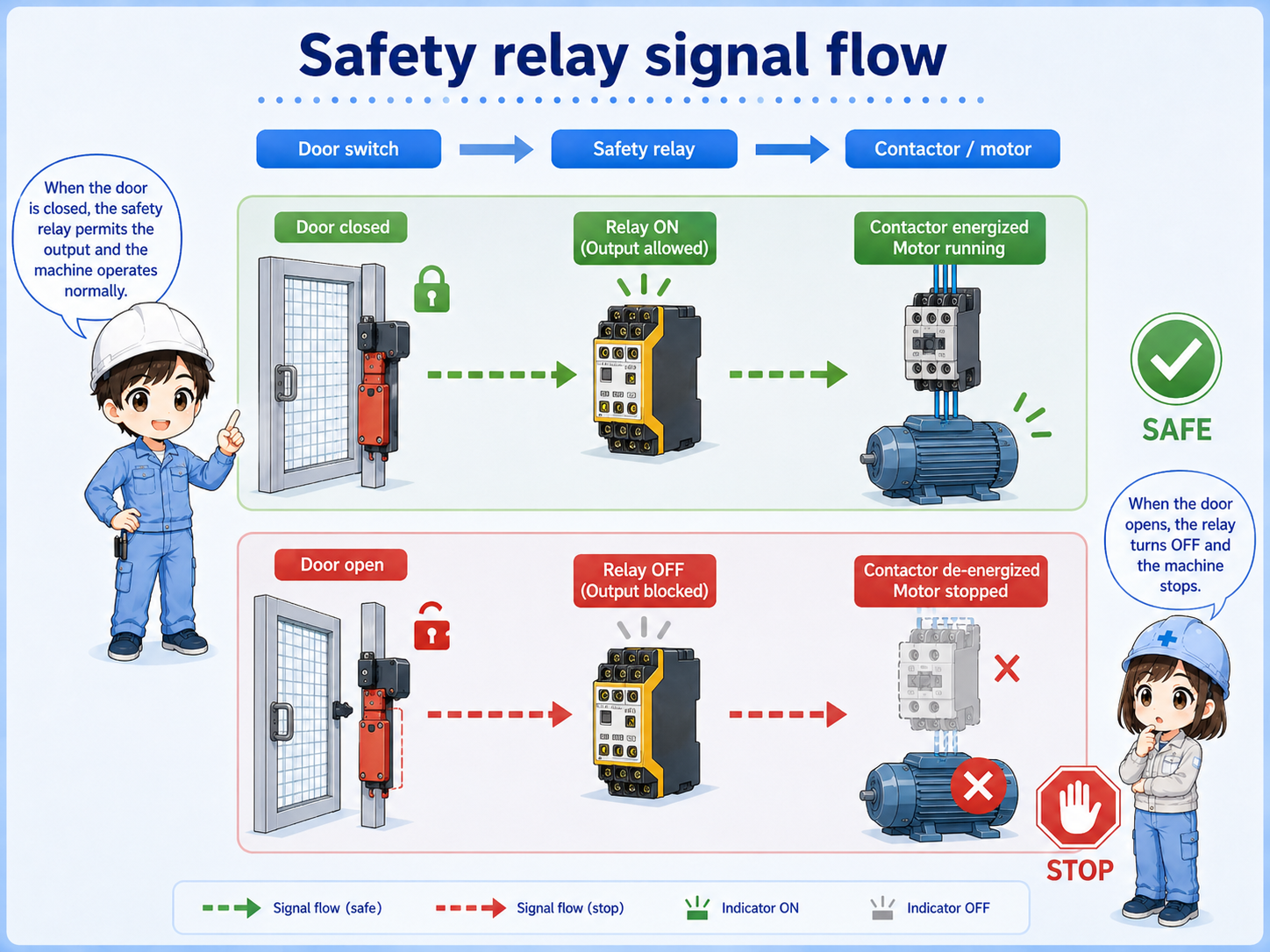
4. Typical signal flow to a safety relay
The safety door switch is usually checked by a safety relay or safety controller, not only by a standard PLC input.
A typical path is: safety door switch → safety relay input channels → safety relay output → contactor, STO, or machine run-permission circuit. When the guard door opens, the input condition is lost and the safety output turns off according to the designed circuit.
1. Door switch
The guard door condition is detected.
2. Safety relay
The input channels are checked.
3. Output path
Run permission, contactors, or STO are controlled.
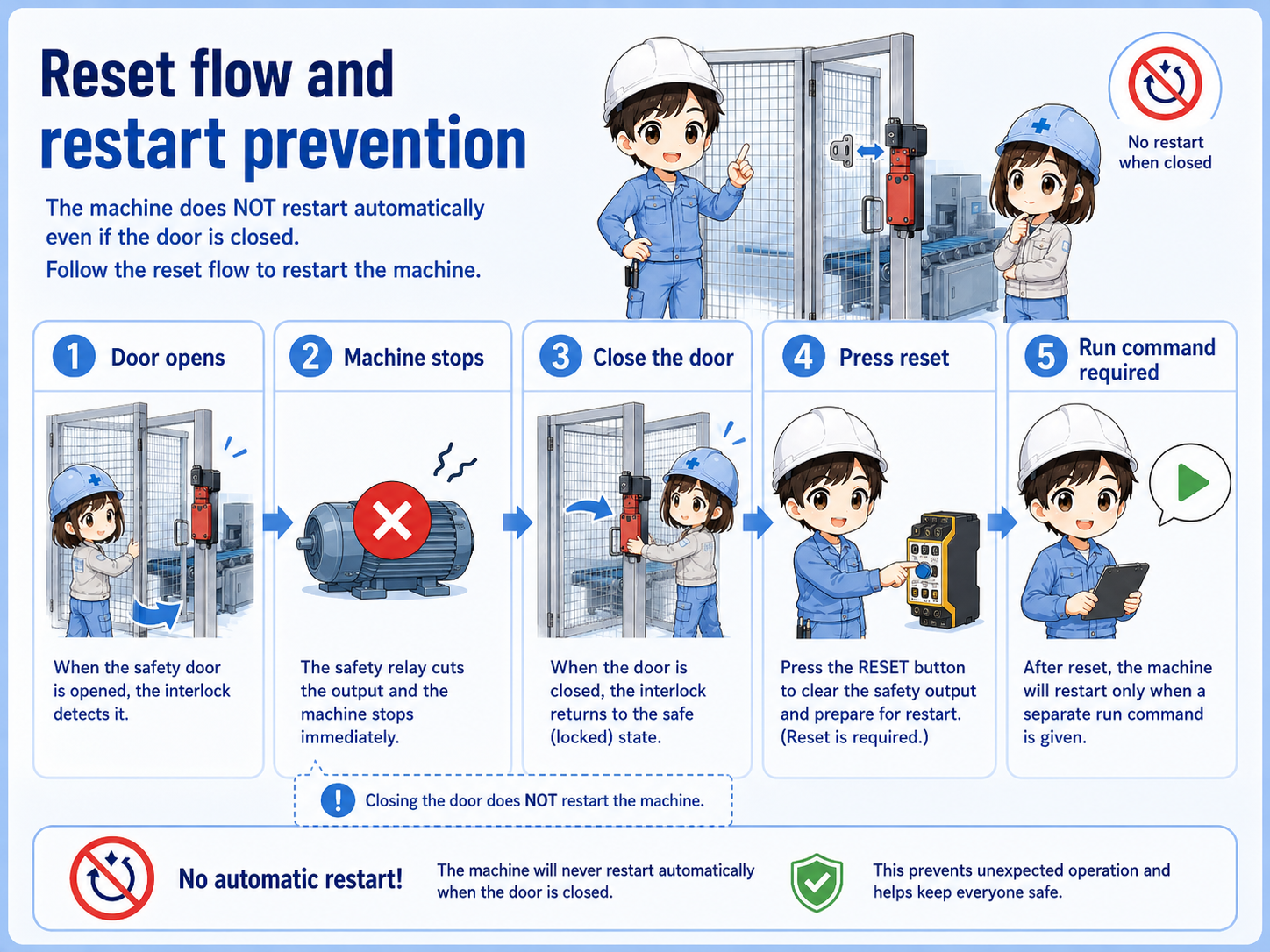
5. Reset and restart are separate ideas
Closing the door should not be treated as the same thing as restarting the machine.
When a safety door is opened, the machine may stop. After the door is closed again, the safety input may return to a valid state, but many machines still require a separate reset operation and then a separate start operation.
This prevents a machine from restarting just because someone closed a guard door. The exact reset method depends on the safety circuit and machine design.
Do not create automatic restart by mistake.
A guard door closing is only one condition. Actual restart behavior must follow the designed safety function, official manuals, and site procedure.
6. Field check points when the safety circuit will not reset
Check the physical door condition, the switch condition, the wiring, and the safety relay inputs in order.
If a machine will not reset after a door was opened, the problem may not be the safety relay itself. The door may not be fully closed, the actuator may be misaligned, one input channel may be missing, or a reset condition may not be satisfied.
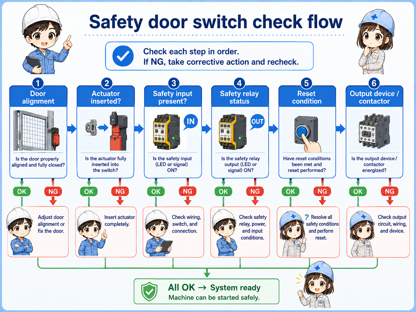
Door fully closed
Check for door floating, misalignment, mechanical interference, or damaged hinges.
Actuator position
Check whether the key or actuator enters the switch correctly.
Switch and cable
Check damage, loose terminals, connector condition, and broken cable possibility.
Safety relay inputs
Check both input channels and the reset condition according to the circuit drawing.
Practical note
Never defeat a safety input for convenience. If the machine must be checked, follow the site's lockout, troubleshooting, and safety procedures.
7. Quick summary
A safety door switch is a safety input for guard door conditions.
A safety door switch monitors whether a guard door is correctly closed and sends that condition to a safety relay or safety controller. It is different from a normal sensor because it is part of the machine's safety-related control path.
For beginner troubleshooting, separate the problem into physical door state, actuator position, switch output, wiring, safety relay input, reset condition, and output path.
Remember this
Do not ask “How can I make the input turn on?” first. Ask “Is the guard condition truly safe and correctly detected?” first.
Related articles
These English articles help connect safety door switches with other control basics.