Good fit for
- Beginners who see speed controllers on air cylinders or pneumatic valves
- Electricians and maintenance staff learning pneumatic cylinder adjustment
- People checking slow, fast, unstable, or uneven air cylinder movement
A pneumatic speed controller adjusts how fast an air cylinder moves by restricting airflow. This guide explains the basic role of a speed controller, meter-out and meter-in control, adjustment screws, and practical field checks.
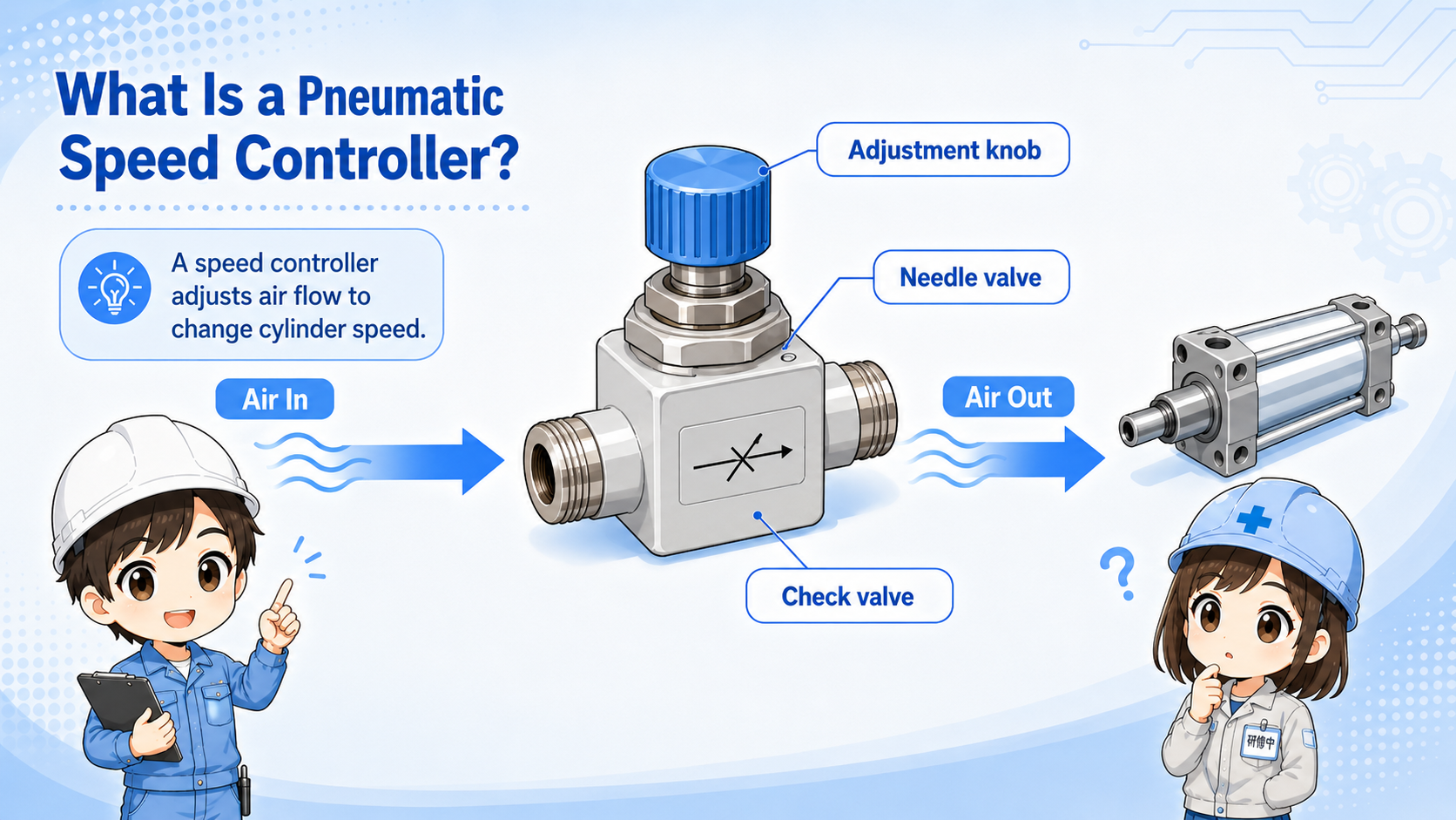
A speed controller adjusts air cylinder speed by restricting airflow through a small adjustable passage.
A speed controller is often used in pneumatic circuits to adjust air cylinder speed by controlling air flow. Depending on the context, it may also be called a pneumatic speed controller or flow control valve. It adjusts flow rather than directly setting air pressure, and the exact adjustment direction, installation method, and usable flow range should be checked in the speed controller manual and pneumatic circuit drawing.
Many speed controllers include a check valve and an adjustable needle. Air can flow freely in one direction and be restricted in the other direction. This makes it possible to control cylinder speed in a practical way.
Do not think of the speed controller as an ON/OFF part. It is a flow adjustment part that changes how smoothly and how fast the cylinder moves.
Cylinder speed affects machine timing, shock, noise, positioning feel, and product handling.
If a cylinder moves too fast, it may hit the end stop hard, shake the mechanism, damage a workpiece, or create unstable machine timing. If it moves too slowly, cycle time may increase or the machine may fail to reach the expected position in time.
Slows motion so the cylinder does not hit the end position too hard.
Helps motion match sensors, valves, and machine sequence timing.
Prevents rough motion when pushing, clamping, lifting, or transferring parts.
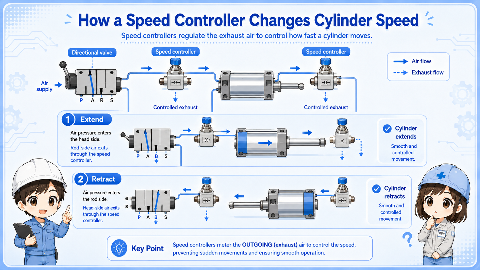
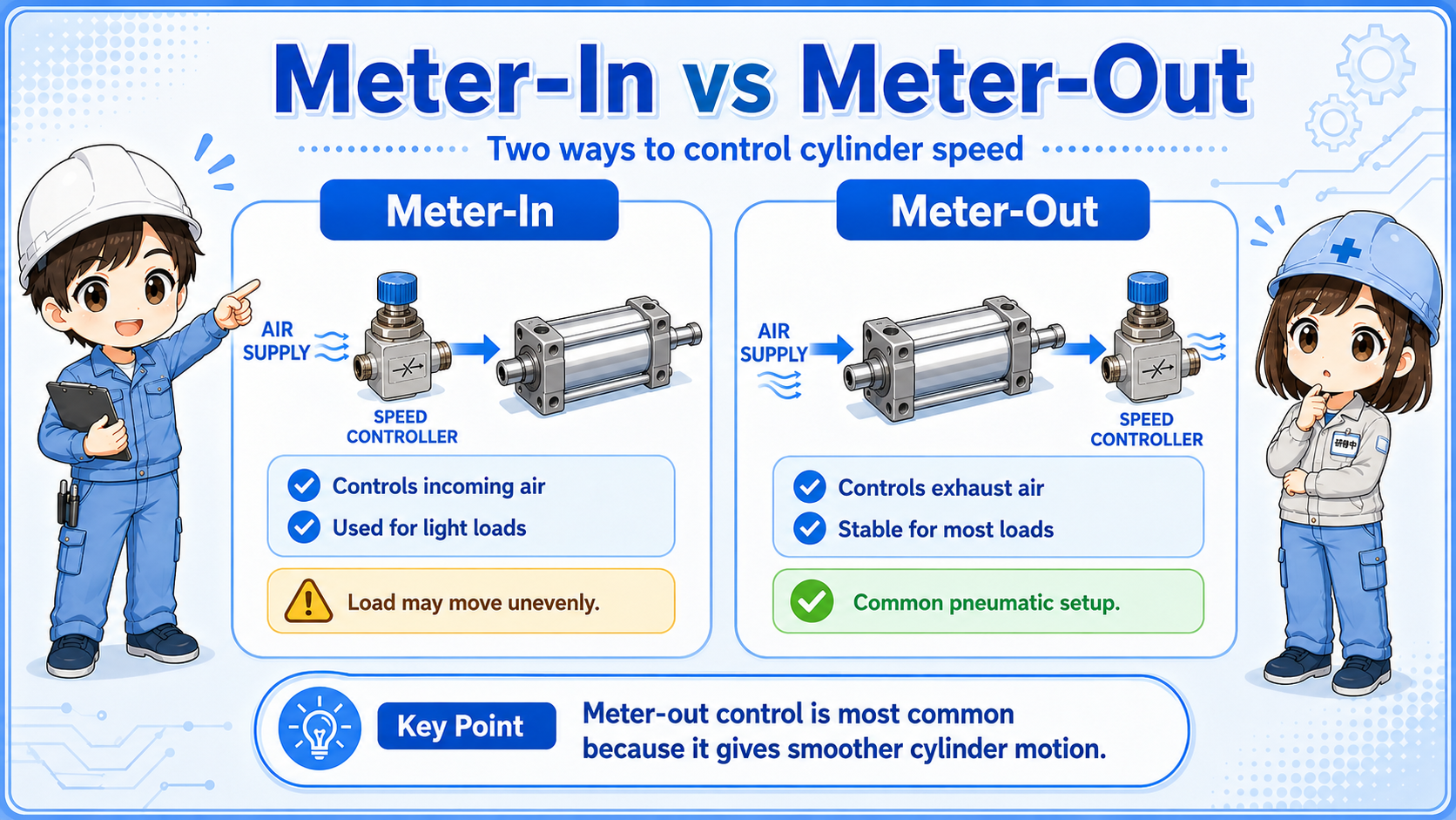
The key difference is whether the speed controller restricts exhaust air or supply air.
Meter-out control restricts the air leaving the cylinder. This often gives more stable motion because the exhaust side resists the cylinder movement. Meter-in control restricts the air entering the cylinder. It may be used in some cases, but it can be less stable depending on load direction and cylinder condition.
| Method | What is restricted? | Beginner viewpoint |
|---|---|---|
| Meter-out | Exhaust air leaving the cylinder | Commonly used for stable cylinder speed control |
| Meter-in | Supply air entering the cylinder | May be used depending on circuit and load, but check stability carefully |
| Free-flow side | Air passes through the check valve side | Direction marking on the part matters |
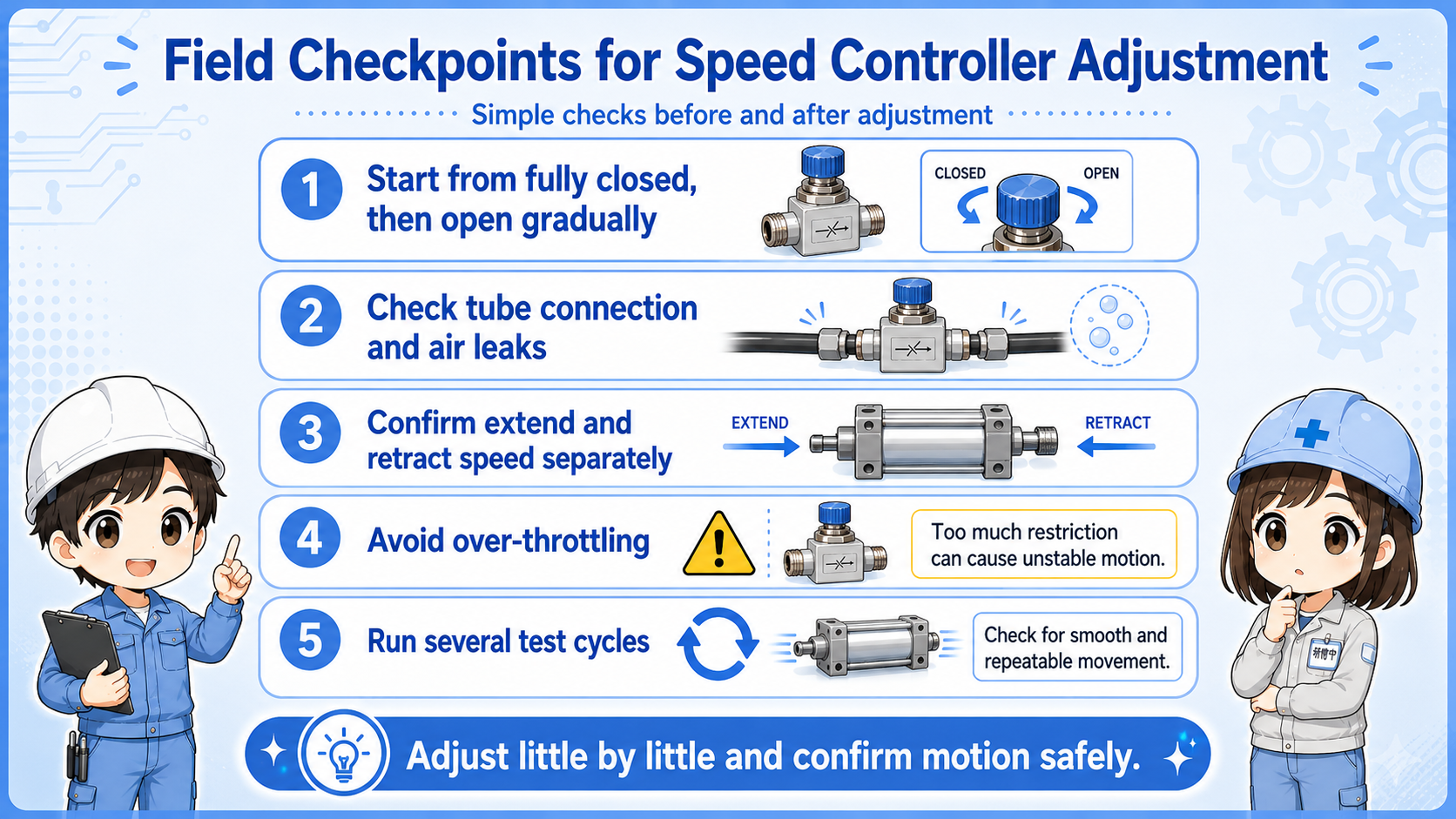
Changing cylinder speed can affect timing, interference, sensor detection, and product handling. Make small changes and confirm the full motion safely.
A safe adjustment starts with understanding the current motion before turning the screw.
A typical adjustment process is: check the current motion → identify extend or retract side → loosen the lock nut if needed → turn the adjustment screw slightly → test the motion → lock the setting again. The exact method depends on the product and machine.
Turning the screw too much at once can make the cylinder suddenly too slow, too fast, or unable to move. Before adjustment, confirm that the moving area is clear and record the original screw position if possible. Small changes are easier to understand and easier to recover from, and speed adjustment should not be used to hide pressure, exhaust, valve, or mechanical problems.
If the motion changed suddenly after maintenance, check whether the speed controller was touched, replaced, installed in the wrong direction, or left unlocked.
A short conversation helps avoid turning the wrong screw without understanding the airflow direction.

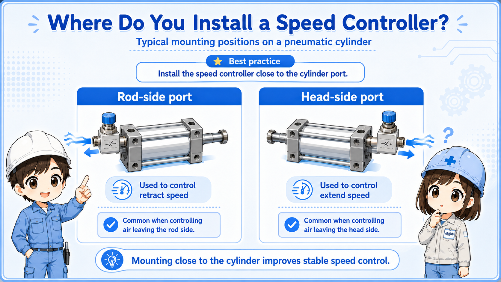
Before turning a speed controller, first confirm whether you want to adjust extension speed or retraction speed. Then check which controller restricts that movement.

So I should not just turn the nearest knob and hope the cylinder gets better?
Exactly. Confirm the movement, airflow direction, current setting, and safety area first. Then adjust a little at a time.
Most practical checks are about adjustment position, tubing, direction, lock condition, and cylinder behavior.
Separate extension and retraction. Check whether only one direction has changed or both directions are unstable.
Check adjustment screw position, lock nut, tamper marks, and whether the setting changed after maintenance.
Check the flow direction marking, meter-out or meter-in installation, tubing route, and cylinder port side.
Check air pressure, valve operation, cylinder load, mechanical friction, tube damage, and muffler clogging.
When adjusting a working machine, follow the site safety procedure and confirm that no hands, tools, or workpieces are in the moving area.