Good fit for
- Beginners learning PLC alarm and reset circuits.
- People who want to understand held alarm bits.
- Technicians checking why an alarm disappears or stays ON.
An alarm hold circuit keeps an abnormal condition visible until a reset action clears it. This guide explains alarm inputs, hold bits, reset signals, lamps, buzzers, and simple ladder logic.
An alarm hold circuit keeps an alarm state active until a reset condition clears it.
An alarm hold circuit is used when an abnormal condition must remain visible even if the original alarm input turns OFF. It prevents a short fault from disappearing before an operator notices it.
In PLC control, this is often made with an internal alarm bit. The alarm input sets the bit, and a reset button or reset condition clears it. The held bit can then drive an alarm lamp, buzzer, message display, or interlock condition.
A direct alarm output only follows the input. An alarm hold circuit stores the alarm state, so the operator can see that an abnormal condition occurred.
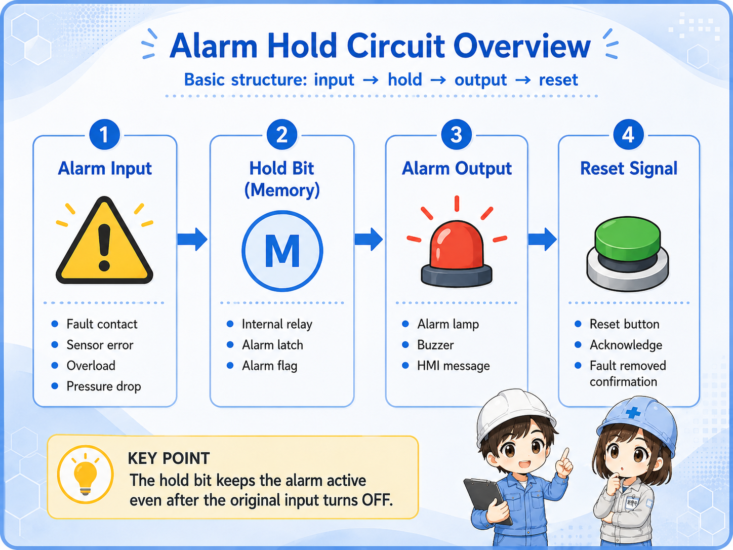
Separate the trigger, memory, output, and clear condition.
| Part | Role | Field image |
|---|---|---|
| Alarm input | The abnormal condition that starts the alarm hold. | Fault contact, overload, pressure drop, sensor error, inverter alarm. |
| Hold bit | The internal memory that stays ON after the alarm is detected. | Alarm latch, internal relay, alarm flag. |
| Alarm output | The lamp, buzzer, display, or output controlled by the held state. | Alarm lamp, buzzer, HMI message, signal tower. |
| Reset condition | The condition that clears the held alarm state. | Reset button, acknowledge button, fault removed confirmation. |
Some machines allow buzzer silence while the alarm remains visible. Others require the abnormal condition to be removed before reset. Always follow the actual machine specification and official documentation.
For beginners, focus on set, hold, output, and reset.
A basic alarm hold circuit usually has two important actions. First, an alarm input sets or holds an internal alarm bit. Second, a reset condition clears that bit. The held bit then drives the alarm lamp, buzzer, or display.

An abnormal input or fault condition turns ON.
The circuit stores that the alarm occurred.
A lamp, buzzer, or message remains visible.
A proper reset condition turns the hold state OFF.
If reset clears the alarm while the abnormal condition still exists, the operator may miss an important problem. In real machines, reset logic must match the machine risk and operating rules.
They look similar, but the purpose is different.
An alarm hold circuit and a self-hold circuit both keep a state ON. The difference is the purpose. A self-hold circuit is often used to keep a machine operation command active. An alarm hold circuit is used to keep an abnormal state visible.
| Item | Self-hold circuit | Alarm hold circuit |
|---|---|---|
| Purpose | Keep an operation command ON. | Keep an alarm state visible. |
| Typical trigger | Start button or operation command. | Fault input or abnormal condition. |
| Typical output | Motor command, relay coil, run state. | Alarm lamp, buzzer, alarm message. |
| Reset / stop | Stop button or stop condition. | Reset button, acknowledge, or fault removed condition. |
The important question is what you are holding. Holding a run command and holding an alarm record have different meanings and different risks.
Many problems come from misunderstanding the reset condition or the held bit.
| Symptom | Likely point to check | Basic idea |
|---|---|---|
| Alarm does not hold | Hold bit, seal-in condition, set condition | Check whether the alarm state is actually stored after the input turns OFF. |
| Alarm does not reset | Reset button, reset permissive, fault still active | Check whether the reset condition is really true and allowed. |
| Alarm resets too easily | Reset rung priority, active fault condition | Check whether reset is clearing the alarm while the abnormal condition remains. |
| Buzzer stops but lamp stays ON | Acknowledge logic and alarm hold logic | This may be intentional if silence and alarm clear are separated. |
Check the alarm input, hold bit, output, and reset path in order.
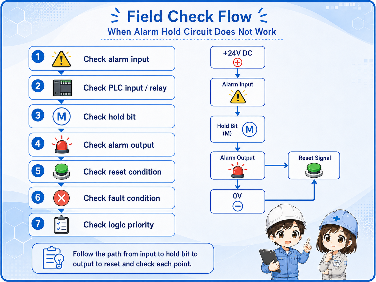

When an alarm hold circuit behaves strangely, first check whether the alarm input, hold bit, and reset condition are changing in the order you expect.

So I should not only look at the lamp or buzzer. I should trace the input, the held bit, and the reset logic one by one.
An alarm hold circuit remembers an abnormal condition until the reset logic clears it.
The abnormal condition that starts the held alarm state.
The internal memory that keeps the alarm active.
The lamp, buzzer, or message controlled by the held state.
The logic that clears the held alarm at the correct timing.
If you can separate these four parts, you can read most basic alarm hold circuits. For real equipment, always confirm the actual PLC program, device wiring, reset rules, and official manuals before changing the circuit.