What is a shielded cable?
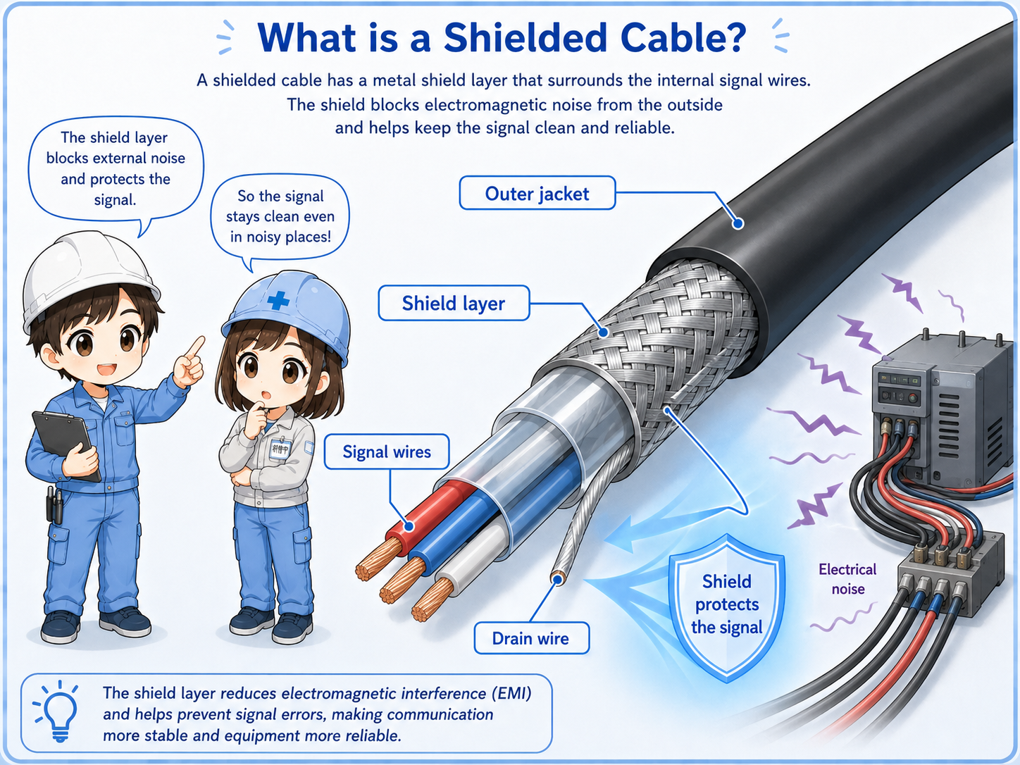
A shielded cable has a conductive shield layer around the internal conductors to help reduce electrical noise influence.
A normal cable carries signals through its internal conductors. A shielded cable adds a conductive layer, such as braided wire, foil, or a combination of both, around those conductors. Some shielded cables also include a drain wire to make shield termination easier. This layer helps reduce the influence of surrounding electrical noise on the signal inside the cable, but the actual construction should be checked in the cable specification.
Shielded cables are often used for analog signals, encoder signals, communication lines, load cell signals, and other weak or sensitive signals. They are also closely related to wiring separation and grounding practices in control panels.
The shield is not magic by itself
A shielded cable only works well when the shield is treated correctly. Routing, grounding, termination, and the connected equipment all matter.
Why electrical noise matters
Sensitive signals can be affected when they run near motors, inverters, solenoids, or other noisy equipment.
Control wiring does not all have the same noise tolerance. A 24 VDC relay output may be relatively strong, while an analog input, encoder pulse, communication line, or load cell signal may be much more sensitive.
If sensitive wiring runs close to high-current or high-speed switching wiring for a long distance, unwanted noise can be induced into the signal. The result may look like unstable values, false inputs, communication dropouts, or intermittent faults.

When a signal is weak or fast, cable treatment becomes important. Shielding, route, and grounding should be checked together.

So if an analog value keeps moving slightly, I should not only look at the PLC program. I should also check the cable route and shield.
Shield grounding ideas
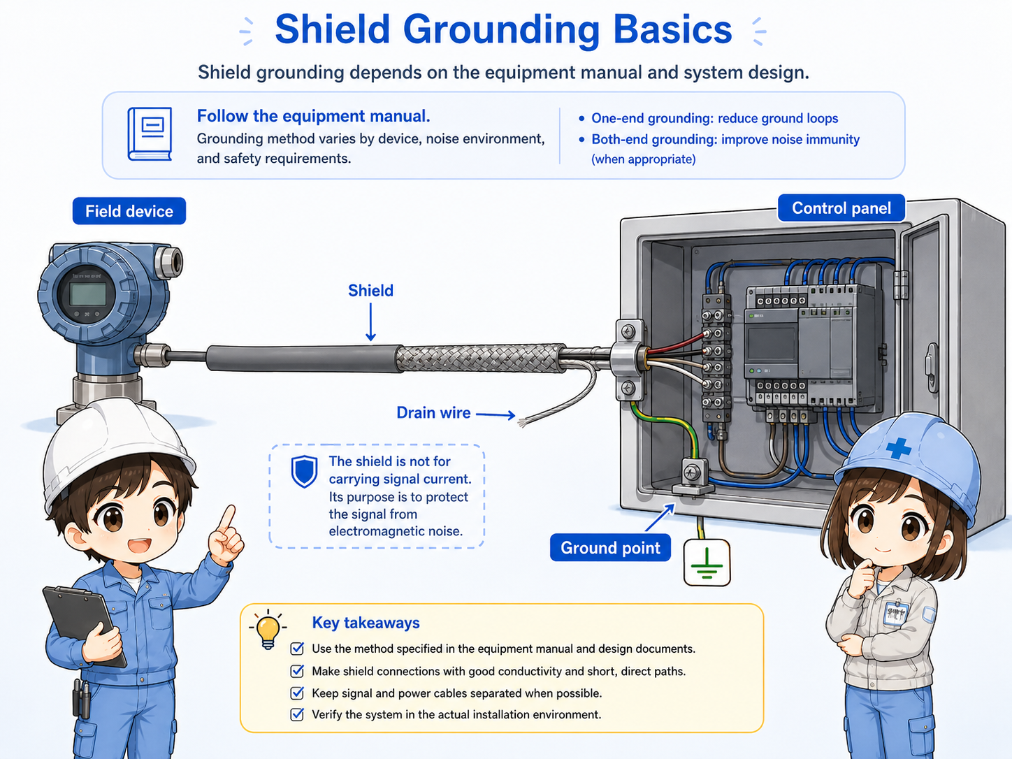
The shield must be connected according to the equipment manual, drawing, or site rule.
A shield needs a path for noise current. Depending on the system, the shield may be connected at one end, both ends, or through a specific grounding method. This is why the drawing and equipment manual should be followed instead of guessing.
| Item | What it means | Field note |
|---|---|---|
| Shield layer | Conductive layer around the internal wires. | Check whether it is properly terminated and not cut back too far. |
| Ground point | Where the shield is connected to earth, frame ground, or signal ground. | Follow the drawing, terminal marking, and equipment manual. |
| Drain wire | A wire connected to the shield for easier termination. | Check whether it is insulated and connected as specified. |
One-end or both-end grounding is not a universal rule
The correct method depends on signal type, equipment, frequency, machine structure, and the manufacturer's instructions.
Routing basics for shielded cables
Shielded cable helps, but poor routing can still create problems.
Even if the cable is shielded, avoid routing it closely beside inverter output wiring, motor power cables, heater power lines, or other noisy wiring for long distances. Shielding and separation should work together.
1. Identify signal type
Analog, communication, encoder, load cell, or other sensitive signal.
2. Choose route
Keep distance from motor, inverter, and high-current wiring where practical.
3. Treat the shield
Connect or insulate the shield according to the drawing or manual.
4. Check symptoms
Relate wiring route and shield treatment to actual signal behavior.
Shielding does not replace wiring separation
If a sensitive cable is routed beside noisy wiring for a long distance, the shield may not fully prevent trouble. Keep both route and shield treatment in mind.
Field checks for shielded cables
When noise-like symptoms appear, check the cable route, shield end, ground point, and terminal treatment together.
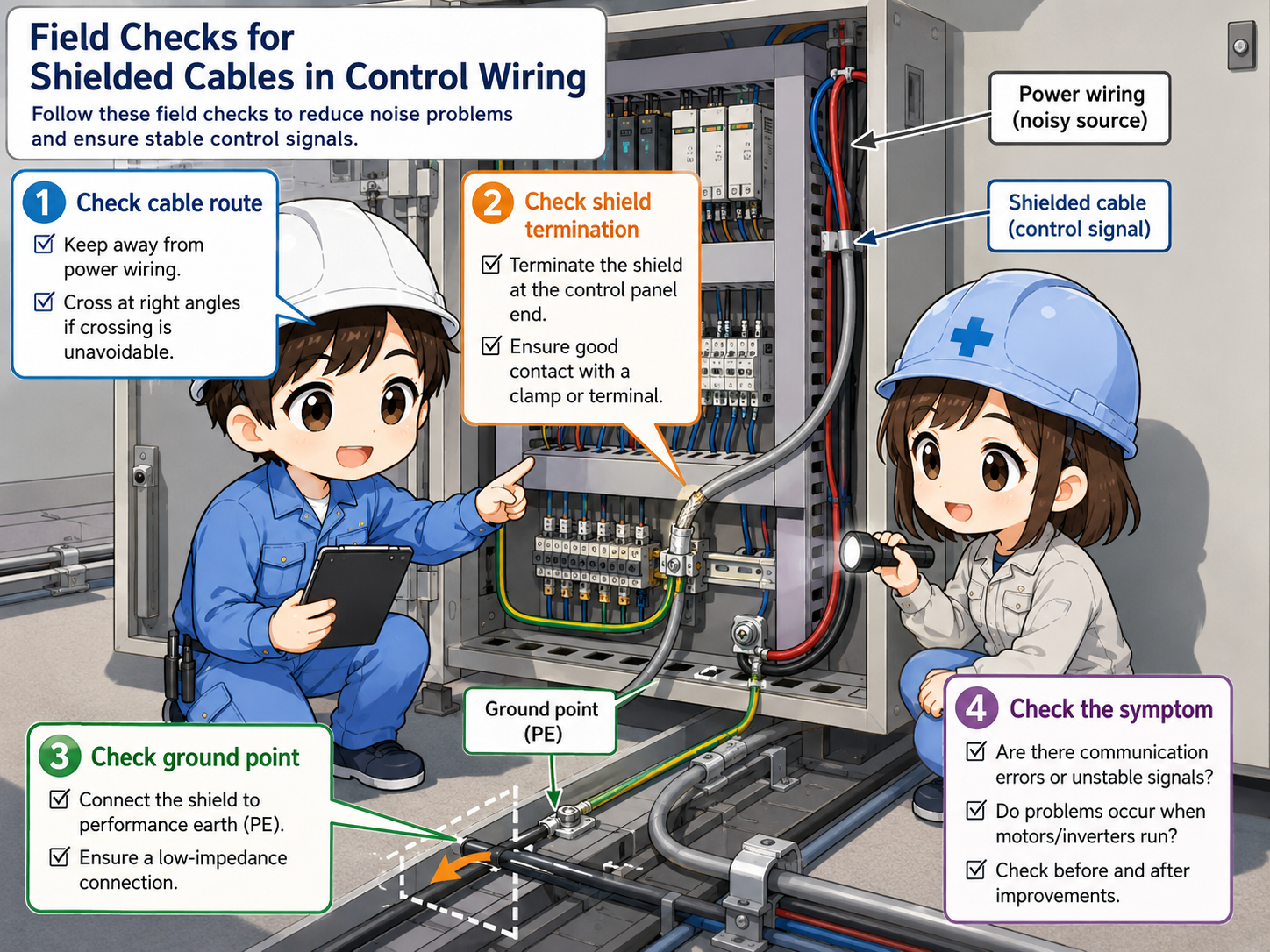
Check cable route
Look for long parallel runs beside inverter, motor, heater, or high-current wiring.
Check shield termination
Confirm whether the shield or drain wire is connected, insulated, or clamped as designed. Also check whether the shield is cut back too far, left floating when it should be terminated, or connected to the wrong terminal. Do not change shield termination without checking the drawing, equipment manual, and site grounding rules.
Check ground point
Verify the terminal marking and grounding method before changing any connection.
Check the symptom
Analog fluctuation, input flicker, encoder errors, or communication faults can guide the inspection.
Common mistakes
Many mistakes come from using shielded cable but not treating the shield correctly.
- Using shielded cable but leaving the shield floating when the drawing requires connection.
- Connecting the shield to a random nearby terminal without checking the manual.
- Running shielded signal cable together with inverter output wiring for a long distance.
- Cutting the shield back too far and exposing sensitive conductors near a noise source.
- Assuming every shield should be grounded in exactly the same way.
Do not change grounding casually
Incorrect grounding can create new problems or safety risks. Follow the drawing, equipment manual, and site procedure.
Summary: shield, route, and ground must work together
A shielded cable helps reduce electrical noise influence on sensitive control signals. It is commonly used for analog signals, communication lines, encoder signals, and other wiring that should not pick up unwanted noise.
The important point is that the cable itself is only one part of the solution. Proper routing, correct shield termination, and the right grounding method are also necessary for reliable control wiring.