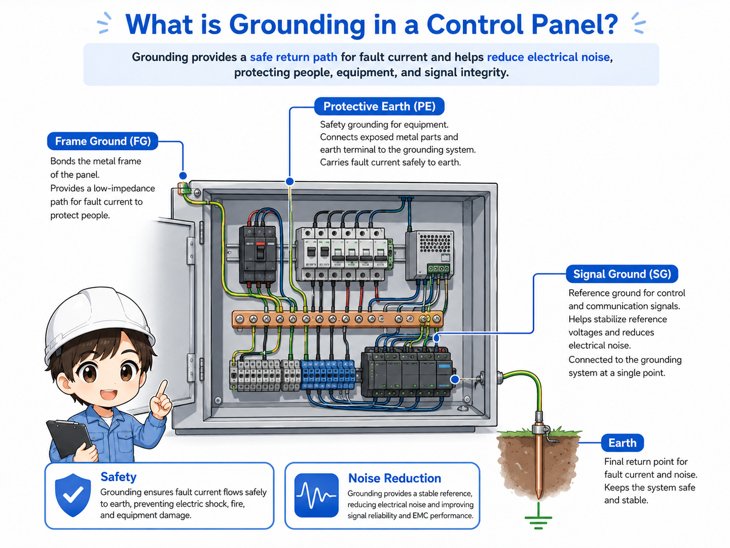
What is grounding in a control panel?
Grounding provides a reference or path for safety, equipment protection, and noise reduction depending on how it is used.
In a control panel, grounding is not just one simple wire. It may include protective earth for safety, frame grounding for equipment bodies, and signal-related grounding for noise reduction or stable signal reference.
The important point is that grounding must be read together with the drawing, terminal labels, equipment manuals, and actual wiring. A green/yellow wire or ground symbol is a clue, but it is not enough by itself.
The simple way to think about it
Grounding is not only “connecting a green wire.” It is a designed path that must match the drawing, equipment manual, and site grounding rules.
Why grounding matters for safety and noise reduction
Grounding has two major practical roles: protecting people and equipment, and helping control systems operate stably.
The safety side is the most important. Protective grounding helps reduce the risk of electric shock if a fault causes a metal enclosure or device body to become energized.
Grounding is also used for noise reduction. In control panels, inverters, servo amplifiers, power supplies, shielded cables, analog signals, and communication lines can be affected by electrical noise. Shielded cables are often used for analog signals, communication lines, encoder lines, and other noise-sensitive signals, but the shield termination method must follow the device manual, wiring diagram, and EMC/noise instructions. Correct grounding and shielding help reduce problems such as unstable signals or communication errors.
Safety
Protective earth helps provide a fault path and reduces shock risk when metal parts become energized.
Equipment protection
Grounding and bonding help keep metal frames and panel bodies at a safer reference potential.
Noise reduction
Proper grounding helps reduce electrical noise entering signals, communication, and sensitive devices.
Stable operation
Incorrect grounding can cause intermittent errors, unstable analog values, or difficult-to-trace failures.

Grounding is easy to overlook because the machine may still run. But when trouble happens, poor grounding can make the symptoms very confusing.

So grounding is not only for safety. It can also affect noise, sensors, communication, and analog values.
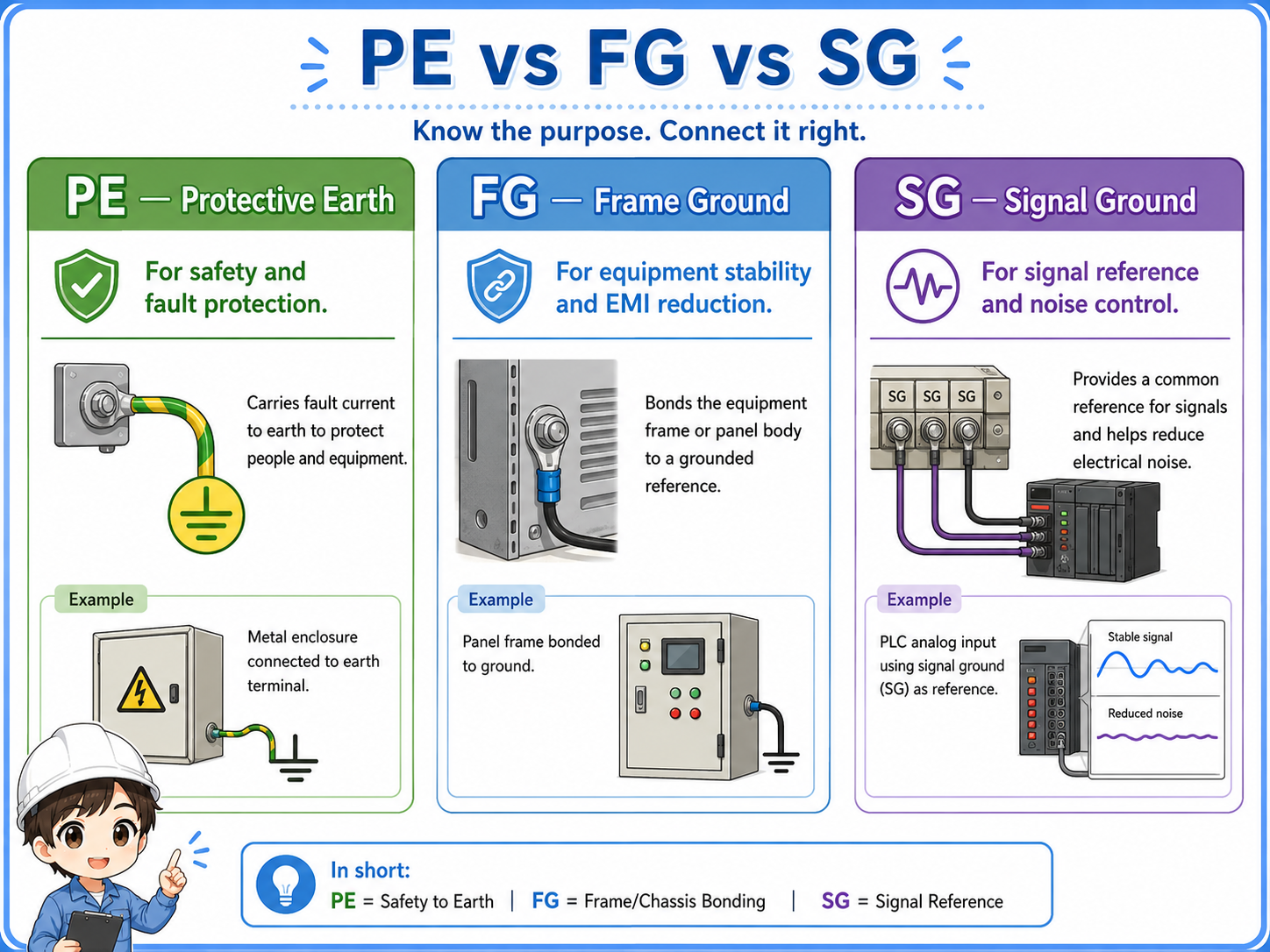
PE, FG, and SG: what they mean
PE, FG, and SG are often seen in control-panel drawings, but their meaning depends on the equipment and design.
In many control systems, PE means protective earth, FG means frame ground, and SG means signal ground. These names are useful, but do not assume they are always connected the same way.
Some devices connect these points internally. Others require an external connection. Some designs separate signal ground from protective earth at certain points to reduce noise loops. Always check the device manual and drawing before changing these connections.
| Label | Common meaning | Practical check |
|---|---|---|
| PE | Protective earth for safety and fault protection. | Check the earth terminal, panel bonding, ground bar, and site grounding rule. |
| FG | Frame ground, often related to metal frames or equipment bodies. | Check whether the device body, mounting plate, and panel frame are bonded correctly. |
| SG | Signal ground or signal reference for control and communication signals. | Check the manual before connecting or separating it from other grounds. |
Names alone are not enough
PE, FG, and SG labels help you read the drawing, but the actual connection must be confirmed with the device manual, drawing notes, and site standard.
How grounding connects with control panel wiring
Grounding should be checked as part of the whole wiring path, not as an isolated wire.
Grounding connects with the control panel body, mounting plate, power supply, inverter, servo amplifier, PLC, shielded cable, field device, and sometimes communication equipment.
When checking a grounding path, look at where the wire starts, where it ends, whether the terminal is tight, whether the metal part is painted or insulated, and whether the drawing shows a direct or separated connection.
1. Drawing
Check ground symbols, PE/FG/SG labels, and connection notes.
2. Terminal
Confirm the ground bar, terminal number, and wire marker.
3. Equipment
Check the grounding point on devices such as power supplies and inverters.
4. Measurement
Confirm continuity and grounding condition according to the site procedure.
Good field habit
When troubleshooting noise or grounding problems, record the drawing point, terminal point, actual wire, and measured result. This prevents guessing and repeated checks.
Field checks for grounding in control panels
Grounding checks should include the drawing, terminal condition, wire condition, bonding, shield treatment, and measurement.
Grounding problems are sometimes visible, but often they are not. A loose terminal, paint under a bonding point, disconnected shield, or incorrect SG connection can cause symptoms that appear only under certain operating conditions.
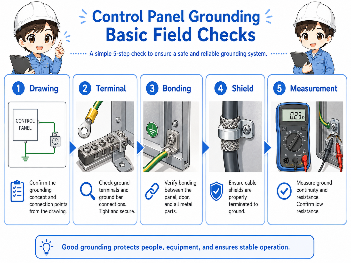
1. Check the drawing
Confirm PE, FG, SG, ground symbols, shield symbols, and connection notes before touching wiring.
2. Check terminals
Look for loose screws, missing ferrules, damaged wires, corrosion, or incorrect terminal positions.
3. Check bonding
Confirm panel body, mounting plate, door, device frame, and ground bar connections.
4. Check shields and signals
For analog or communication issues, check shield termination and signal-ground treatment carefully. Do not move shield wires randomly; confirm where the shield is connected, whether the drawing or manual specifies the panel side, device side, or another grounding point, and record the condition before changing it according to site grounding rules.
Do not change grounding casually
Changing a grounding connection may affect safety, noise behavior, communication stability, or measurement accuracy. Follow the equipment manual, drawing, and site rules.
Common mistakes to avoid
Many grounding mistakes come from treating all grounds as the same thing.
- Assuming PE, FG, and SG are always connected in the same way.
- Removing a ground wire because the machine still appears to operate.
- Connecting shield wires randomly without checking the drawing or manual.
- Ignoring paint, rust, or loose bolts at bonding points.
- Judging grounding only by wire color without checking the actual path.
- Trying to solve noise problems by changing ground connections without records.
Simple field mindset
Treat grounding as a designed path. Read the drawing, check the terminal, confirm the equipment manual, and measure according to the site procedure.