Why separate power wiring and signal wiring?
The goal is to reduce electrical noise coupling from high-energy wiring into low-level signals.
In a control panel, not all wires have the same role. Motor wiring, heater wiring, inverter output wiring, and main power lines can carry larger current, switching energy, and electrical noise. Sensor wiring, analog signals, communication cables, and PLC input wiring often carry much smaller signals.
If these different wires are bundled together for a long distance, noise can couple into the signal wiring. This can cause symptoms such as unstable sensor inputs, analog value fluctuation, communication errors, or hard-to-repeat machine faults.
Separation is a practical noise-reduction habit
It does not mean every wire must be far apart. It means you intentionally separate high-energy wiring from weak or sensitive wiring where the panel layout allows it.
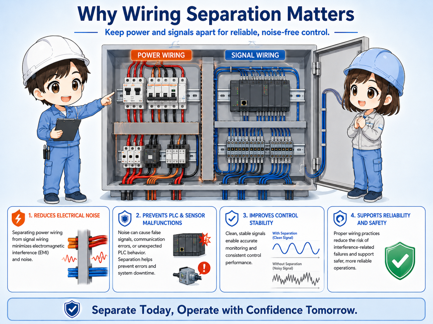
Power wiring and signal wiring are different
Start by identifying what kind of wire you are looking at before deciding the route.
| Wire group | Typical examples | Why it matters |
|---|---|---|
| Power wiring | Main power, motor power, heater power, inverter output, solenoid loads. | Can carry larger current, switching noise, and electromagnetic influence. |
| Signal wiring | Sensor inputs, PLC inputs, analog signals, encoder lines, communication cables. | Can be affected by noise because signal levels are smaller or more sensitive. |
| Control power wiring | 24 VDC power for sensors, PLC power, relay control wiring. | Often sits between power and signal, so routing should be decided by the actual circuit. |
Power wiring vs signal wiring is not decided only by voltage level. Current, switching behavior, signal level, and sensitivity also matter. For example, 24 VDC wiring may be control power, a PLC input signal, or a sensor supply depending on the circuit, so the drawing and terminal labels should be checked before choosing the route.

Before routing a wire, ask what it carries. A motor line and a sensor input line may both look like wires, but their influence on the panel is very different.

So I should not choose the shortest route only. I should also think about what other wires run beside it.
Basic routing ideas
Keep sensitive wiring away from noisy wiring, especially when they would run parallel for a long distance.
The most important habit is to avoid long parallel runs between power wiring and signal wiring. A short right-angle crossing is usually cleaner than running side-by-side through the same duct for a long distance, but it is not a guarantee that noise problems will disappear. Exact separation distance and routing rules should follow the panel drawing, wiring standard, equipment manual, and EMC/noise instructions.
1. Identify wire type
Power, motor, signal, analog, communication, and 24 VDC control wiring.
2. Choose route
Use separate duct paths or separate duct areas where possible.
3. Avoid parallel runs
Do not run noisy and sensitive wires together for long distances.
4. Cross cleanly
If crossing is necessary, make it short and preferably at a right angle.
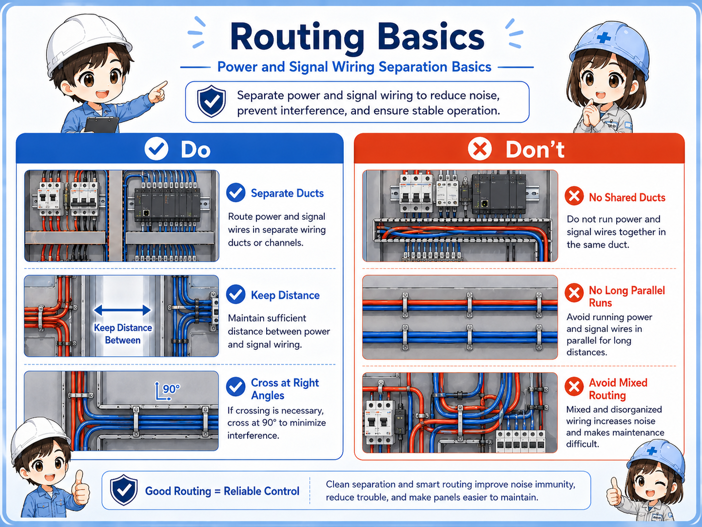
Wiring duct layout in a control panel
Wiring ducts make the panel tidy, but mixing every wire in one duct can create troubleshooting problems.
In many panels, ducts are used to route wires around PLCs, terminal blocks, relays, breakers, inverters, and power supplies. A neat panel is helpful, but the duct route should still respect wiring type.
One common idea is to keep signal and PLC input wiring on one side and power or load wiring on another side. The exact layout depends on the panel, but the intent is the same: avoid unnecessary mixing.
Panel drawings and site rules come first
Use the site's panel standards, drawings, and equipment manuals as the primary rule. This guide explains the basic reason behind the separation habit.
Field checks for wiring separation
When noise-like problems appear, check wiring routes together with grounding, shielding, and equipment conditions.
Wiring separation is one part of noise troubleshooting. If a problem appears only when a motor starts, an inverter runs, or a high-current load switches, the routing between noisy wiring and sensitive wiring is worth checking.
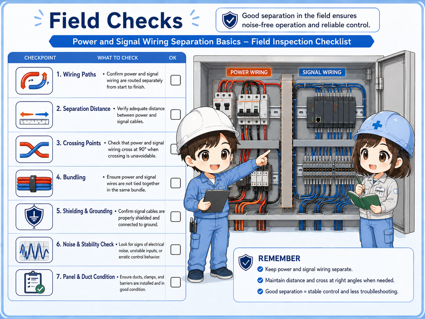
Check long parallel runs
Look for sensor, analog, or communication cables running beside motor or inverter wiring.
Check crossing points
Short right-angle crossings are usually cleaner than long side-by-side routes.
Check shields and grounds
Shielded cables only help when their shield treatment follows the design or manual.
Check symptoms
Relate wiring routes to actual symptoms such as analog fluctuation, input flicker, or communication errors.
Common mistakes
Noise problems often become hard to solve when wiring routes are chosen only for appearance or shortest distance.
- Running inverter output cables and sensor cables together in the same duct for a long distance.
- Routing analog signals near high-current load wiring without checking the manual.
- Assuming a neat-looking duct is always electrically clean.
- Using shielded cable but treating the shield end incorrectly.
- Changing PLC logic before checking whether the input signal itself is unstable.
Follow electrical safety procedures
Control panels can contain dangerous voltage. Do not open or modify wiring unless you are qualified and following the site's lockout, isolation, and verification procedure.
Summary: separate by role, not by appearance
Power wiring and signal wiring should be separated because they carry different kinds of electrical energy. High-current or switching wiring can influence weak signal wiring when they are routed too closely for too long.
In practice, identify the wire type, avoid long parallel runs, cross cleanly when necessary, and check shielding or grounding according to the design. This makes control panels easier to troubleshoot and helps reduce noise-related problems.