Good fit for
- Beginners who see IAI RoboCylinders or electric actuators in machines
- Electricians learning the difference between air and electric cylinders
- People checking PLC commands, position numbers, complete signals, or alarms
An IAI RoboCylinder is an electric actuator that moves to commanded positions through a controller. This guide explains how it differs from an air cylinder, how PLC signals are used, and what to check around homing, position numbers, complete signals, and alarms.
An IAI RoboCylinder is an electric actuator that moves to target positions under controller command.
An IAI RoboCylinder is used when a machine needs controlled linear motion. Unlike a simple air cylinder, it uses a motor, encoder, mechanical drive, and controller to move to a commanded position.
In many machines, the PLC does not directly drive the actuator motor. The PLC sends command signals or position numbers to the controller, and the controller operates the RoboCylinder.
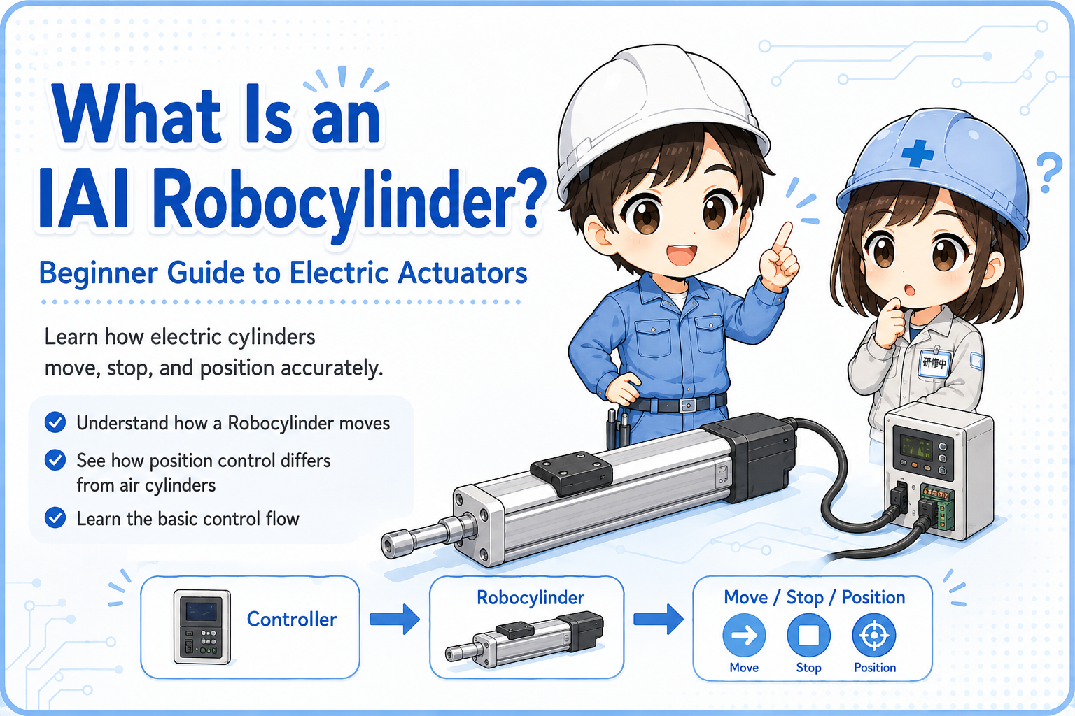
The PLC gives instructions. The controller manages the motion. The RoboCylinder moves according to the selected position or command.
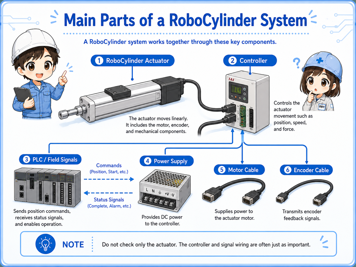
The system is easier to read when you separate the actuator, controller, PLC signals, and power.
A typical RoboCylinder setup includes the actuator body, controller, motor cable, encoder cable, power supply, and PLC I/O or communication wiring. The exact structure depends on the model and controller type.
Moves the slider or rod to the commanded position.
Receives commands, controls the motor, and outputs status signals.
Sends start, position, reset, and other commands; reads complete or alarm signals.
An air cylinder is usually simpler, while a RoboCylinder gives more controllable positioning.
An air cylinder moves by air pressure and valve control. It is often used for simple extend/retract motion. A RoboCylinder moves electrically and can stop at registered positions, control speed, and report operation status through the controller.
| Item | Air cylinder | IAI RoboCylinder |
|---|---|---|
| Drive source | Compressed air | Motor and controller |
| Typical motion | Extend / retract with simple end positions | Move to registered or commanded positions |
| Field viewpoint | Check air pressure, valve, speed controller, and sensors | Check controller status, homing, position number, complete signal, and alarms |
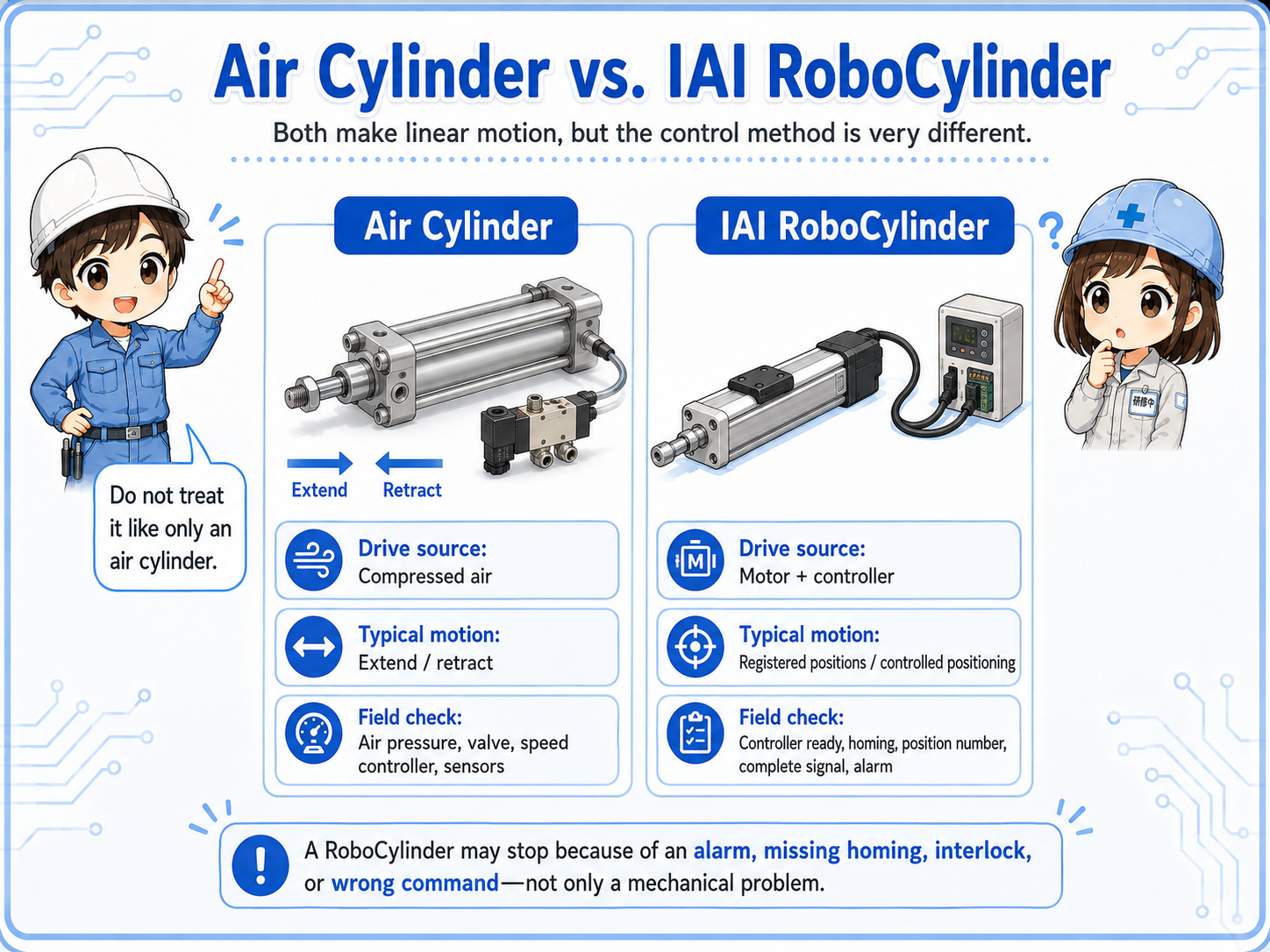
If a RoboCylinder does not move, the cause may be controller alarm, missing homing, incorrect position command, interlock, or parameter condition—not only a mechanical problem.
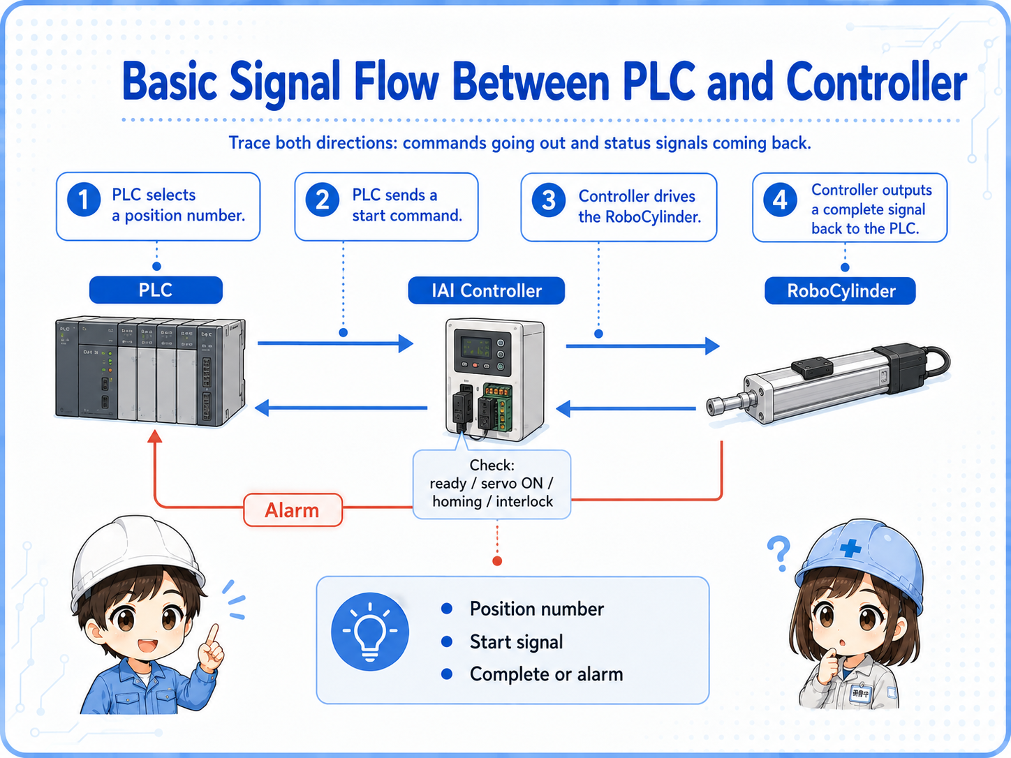
Troubleshooting becomes easier when you trace command, operation, completion, and alarm signals.
A simple flow may be: PLC selects a position number → PLC sends a start command → controller drives the RoboCylinder → controller outputs a complete signal. If something is wrong, the controller may output an alarm or refuse to start until conditions are satisfied.
Before assuming the actuator is broken, check whether homing is complete, the correct position number is selected, start timing is valid, interlocks are satisfied, and alarm status is normal.
For many RoboCylinder issues, the key is not only “is there power?” but “what state is the controller in?”
A short conversation helps separate motion problems from signal and controller problems.

If a RoboCylinder does not move, do not check only the actuator. Look at the controller status first: power, servo state, homing, alarm, and whether the start command is accepted.

So even if the PLC output turns ON, the actuator may not move if the controller is not ready?
Exactly. Check command, controller ready state, position number, complete signal, alarm, and mechanical load in order.
Most practical checks are about controller state, commands, position data, cables, and mechanical load.
Check power, servo ON, ready signal, alarm display, emergency stop, and reset condition.
Check home return status, home position, origin completion signal, and whether operation requires homing first.
Check position number, start signal timing, interlocks, PLC output wiring, and complete signal feedback.
Check motor cable, encoder cable, mechanical jam, load condition, guide resistance, and abnormal noise.
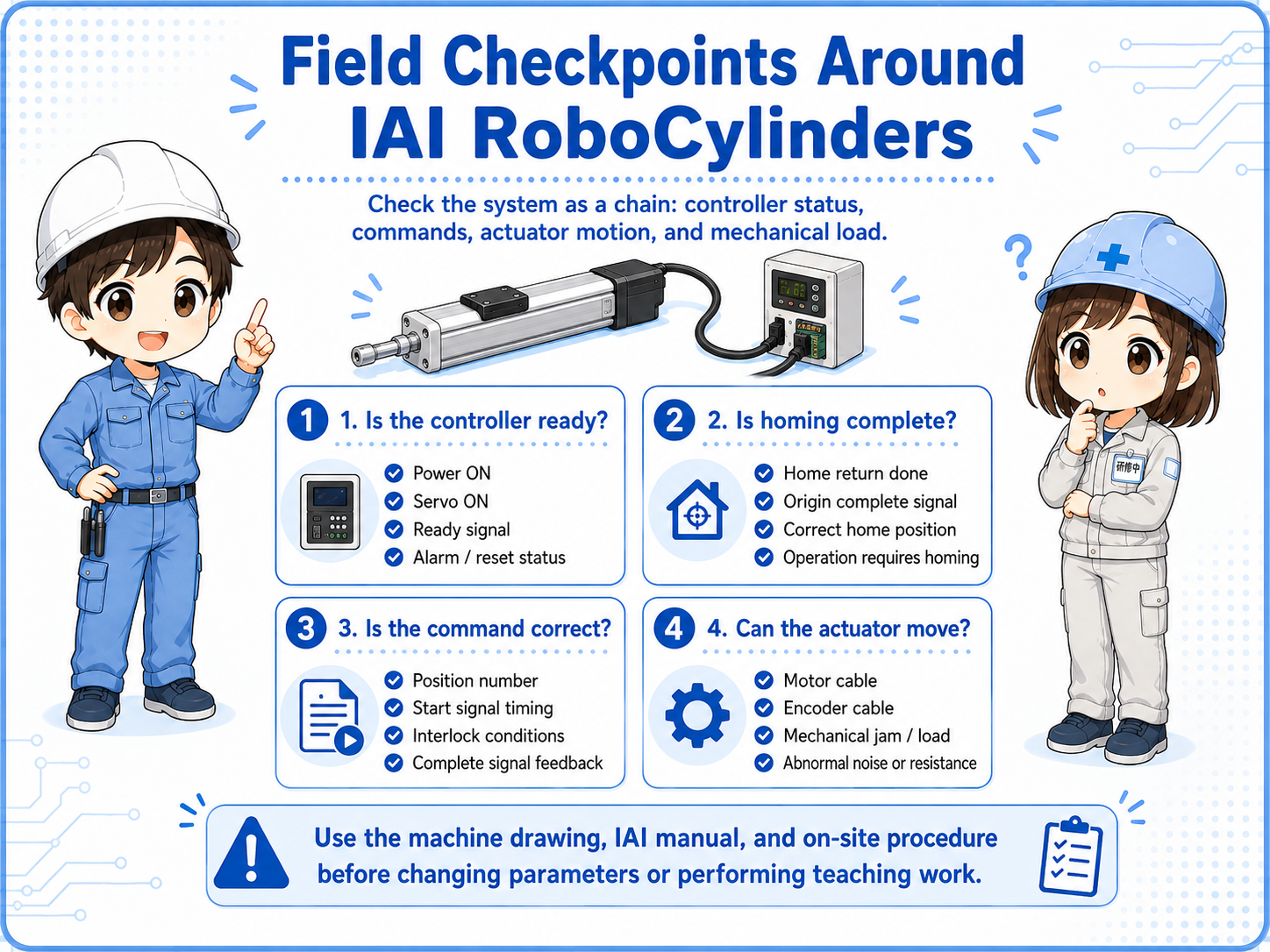
IAI models and controllers differ by series. Use the machine drawing, IAI manual, and on-site procedure before changing parameters or performing teaching work.