What is an analog output?
An analog output is a PLC output that sends a continuously changing command value.
A normal digital output turns a device ON or OFF. An analog output is different. It sends a variable signal such as 0-10V or 4-20mA so that the receiving device can change speed, opening, power, position, or another controlled amount.
In control panels, analog output modules are often connected to inverters, control valves, temperature controllers, or other analog devices. The PLC sends a command value, and the receiving device turns that value into actual machine behavior.
The basic idea
Digital output answers “turn it ON or OFF.” Analog output answers “how much should it operate?” That difference is the first point to understand.

With analog output, the PLC is not only switching a device. It is sending a command amount.

So it is used when the PLC wants to control speed or valve opening gradually?
Exactly. The PLC sends a changing signal, and the receiving device interprets it as a command.
Digital output vs analog output
Digital outputs switch states. Analog outputs send command amounts.
| Item | Digital output | Analog output |
|---|---|---|
| Main meaning | ON or OFF command | Changing command value |
| Typical devices | Indicator lamp, relay coil, solenoid valve, buzzer | Inverter speed command, control valve opening command, analog controller input |
| PLC data | Bit value such as ON/OFF, 1/0, TRUE/FALSE | Numeric command value converted into voltage or current output |
| Common field signals | 24V DC output signal | 0-10V, 1-5V, 4-20mA, 0-20mA |
Simple way to remember
If the PLC only needs to turn something ON, it is usually digital. If the PLC needs to decide how fast, how open, or how much, it is usually analog.
0-10V and 4-20mA analog output basics
The same signal names appear in analog input, but here the PLC is sending the signal out.
A 0-10V analog output changes its voltage according to the command value. A 4-20mA analog output changes its current according to the command value. The receiving device must be set to the same signal type.
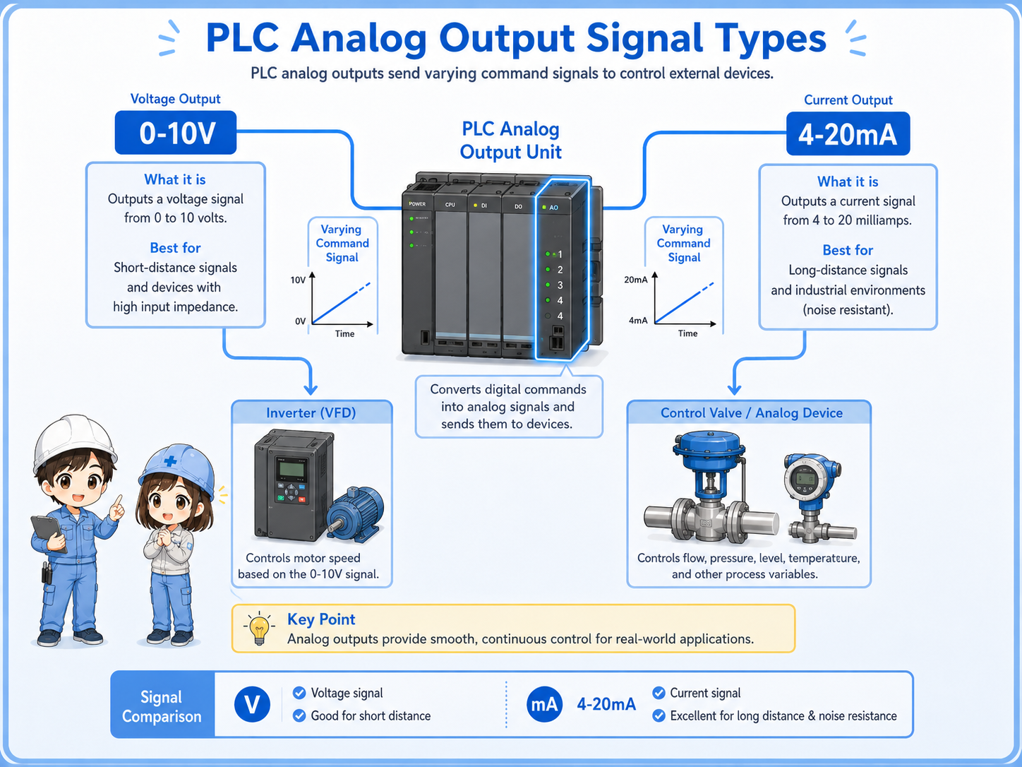
0-10V output
The PLC changes voltage between 0V and 10V. It is often used as a speed or level command.
4-20mA output
The PLC changes current between 4mA and 20mA. It is common in industrial analog control.
Output range setting
The analog output module and receiving device must use the same range.
Receiver setting
An inverter or valve controller may need its input type and scaling set separately.
Control flow: set value → analog output → machine action
Analog output is often used to turn a PLC numeric command into actual machine movement.
For example, a PLC may calculate a speed command. The analog output module converts that command into 0-10V. An inverter receives the signal and changes motor speed. In another case, a PLC may output 4-20mA to control a valve opening.
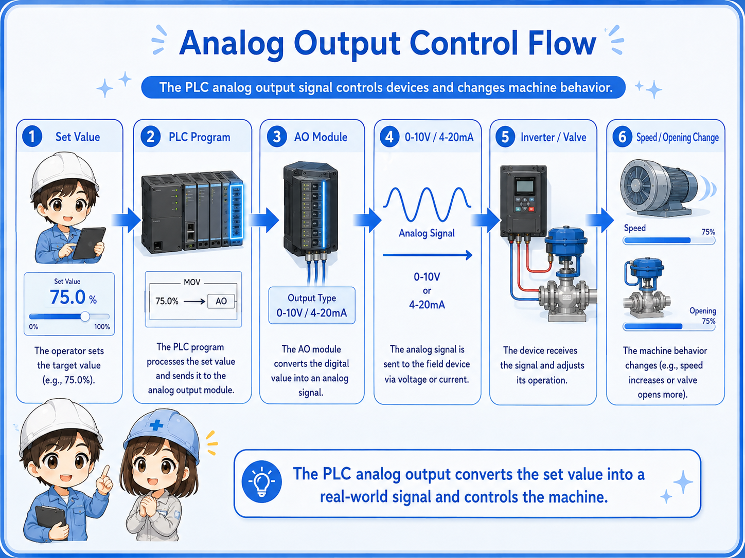
1. Program decides
The PLC calculates or receives a command value.
2. Scaling applies
The command is converted into an output range.
3. AO module sends
The analog output module sends voltage or current.
4. Device receives
The inverter, valve, or controller reads the signal.
5. Machine changes
Speed, opening, power, or another amount changes.
| Example | Low command | High command | Meaning at device side |
|---|---|---|---|
| Inverter speed command | 0V | 10V | Low speed to full speed |
| Control valve command | 4mA | 20mA | Closed or minimum opening to full opening |
| Analog controller command | 0V or 4mA | 10V or 20mA | Minimum command to maximum command |
Important point
The PLC value, analog output signal, and receiving device behavior must all use the same meaning. If one range is different, the machine may move differently than expected.
Field check points for analog output problems
When the device does not respond correctly, check the PLC command, AO range, wiring, receiver setting, and measured signal in order.
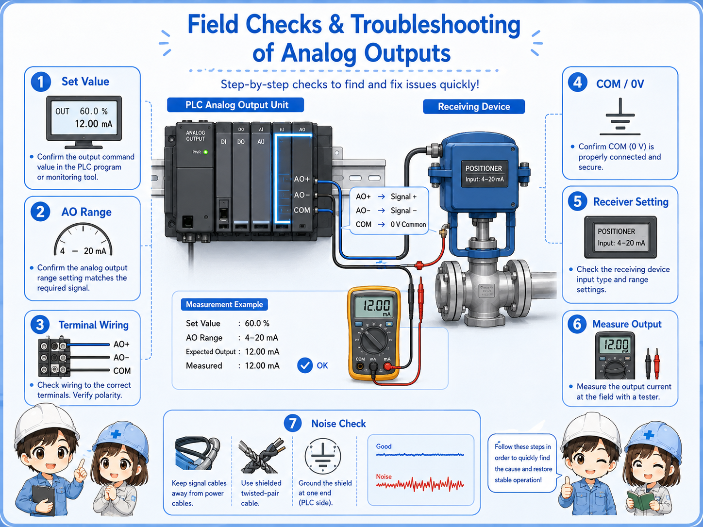
PLC command value
Check what value the PLC is trying to output before checking only the wiring.
AO range setting
Confirm whether the module is set for voltage or current output.
Receiving device setting
Check whether the inverter, valve, or controller is set to receive the same signal type.
Measured output signal
Measure the actual voltage or current carefully and compare it with the PLC command.
Do not force an output without understanding the machine impact
Analog output may change speed, valve opening, pressure, or flow. Forcing or changing the value can move equipment unexpectedly.
Common mistakes with analog outputs
Many analog output problems come from range mismatch, reversed wiring, receiver settings, or scaling mismatch.
| Mistake | Why it causes trouble | Better check |
|---|---|---|
| Voltage/current mismatch | The PLC may output 0-10V while the receiver expects 4-20mA, or the opposite. | Check both the PLC AO setting and the receiving device input setting. |
| Scaling mismatch | The PLC command value and the receiver range may not mean the same thing. | Compare PLC scaling, output signal, and receiving device parameter range. |
| Checking only the PLC monitor | The monitor may show a command value, but the actual output terminal may be different. | Measure the actual output signal at the terminal when safe to do so. |
| Ignoring noise and shield wiring | Analog output can be affected by wiring route, noise, and grounding/shield treatment. | Check cable route, shield handling, and separation from power wiring. |
Beginner-friendly rule
When analog output seems wrong, separate the problem into three parts: PLC command, actual output signal, and receiving device response.
Safety notes before checking analog output wiring
Analog output signals may be low voltage or low current, but the command can affect real machine movement.
Always follow the site rules and drawings. Do not change output values, scaling, inverter settings, valve settings, or wiring unless you understand how the machine will respond.
If the analog output controls motor speed, valve opening, heater output, pressure, flow, or another process amount, an incorrect command may cause unsafe operation.
Analog output can move equipment
Treat analog output checks carefully. Even a small change in signal may change speed, opening, pressure, temperature, or flow depending on the system.